Mojave — Build Guide
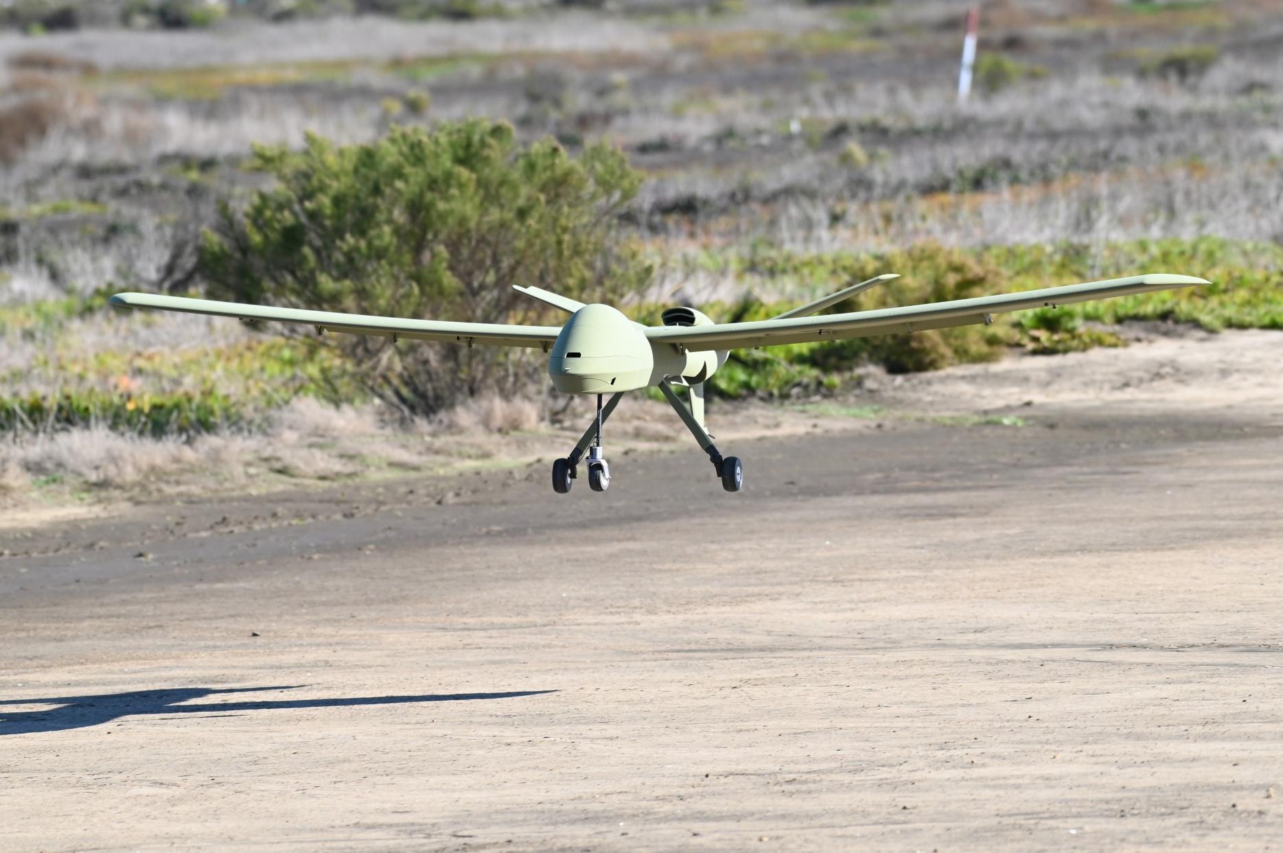
At a glance
- Difficulty: Intermediate to build, easy to fly
- Wingspan: 3000 mm (118")
- Length: 1650 mm (65.0")
- Flying weight: 7700–8200 g (17–18 lb)
Overview
Thank you for purchasing a model by Lofted Aero! 3D printed aircraft are an exciting new segment of the hobby, and we've got no shortage of ideas for new designs. Your support helps us make those reality.
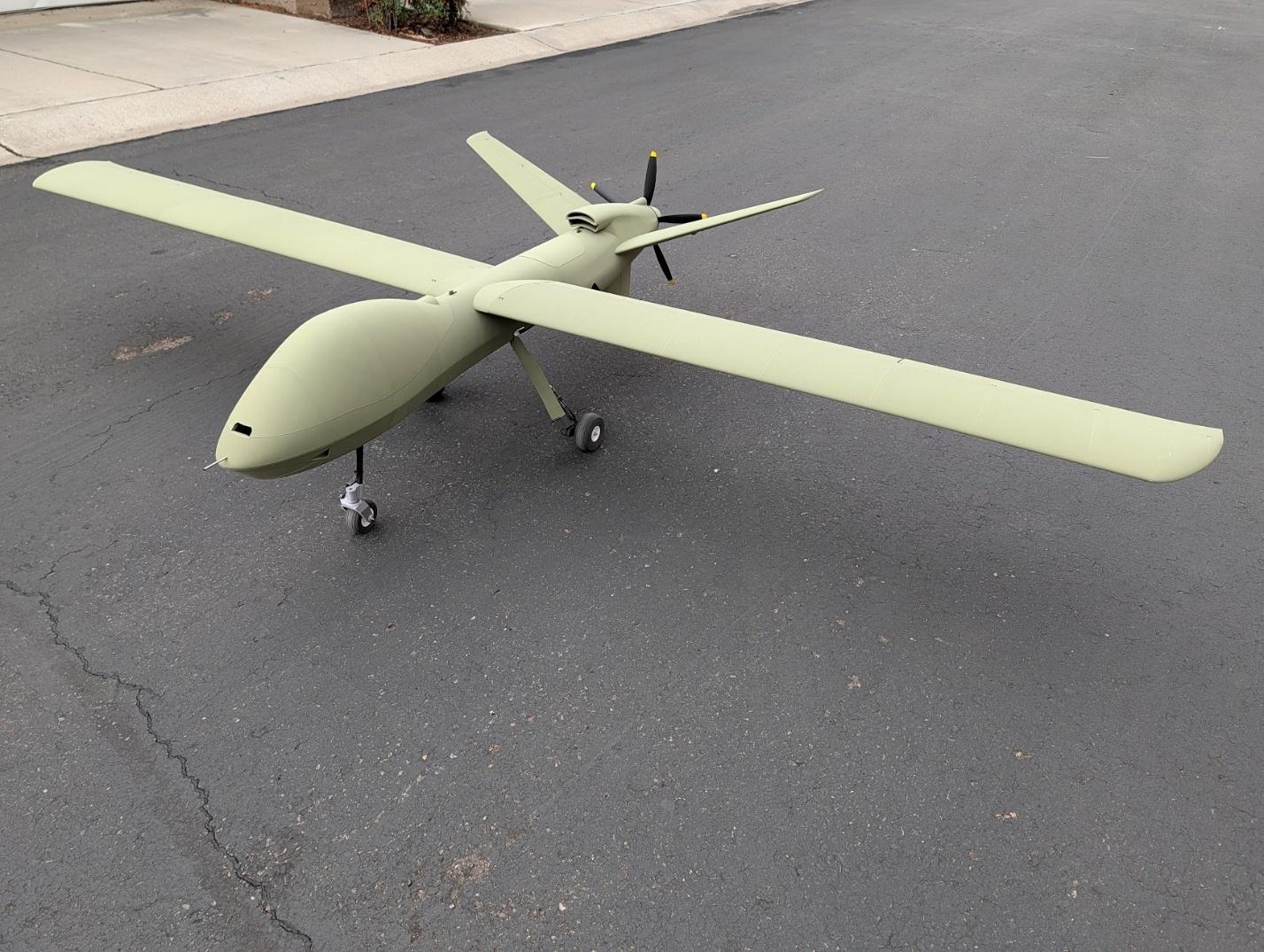
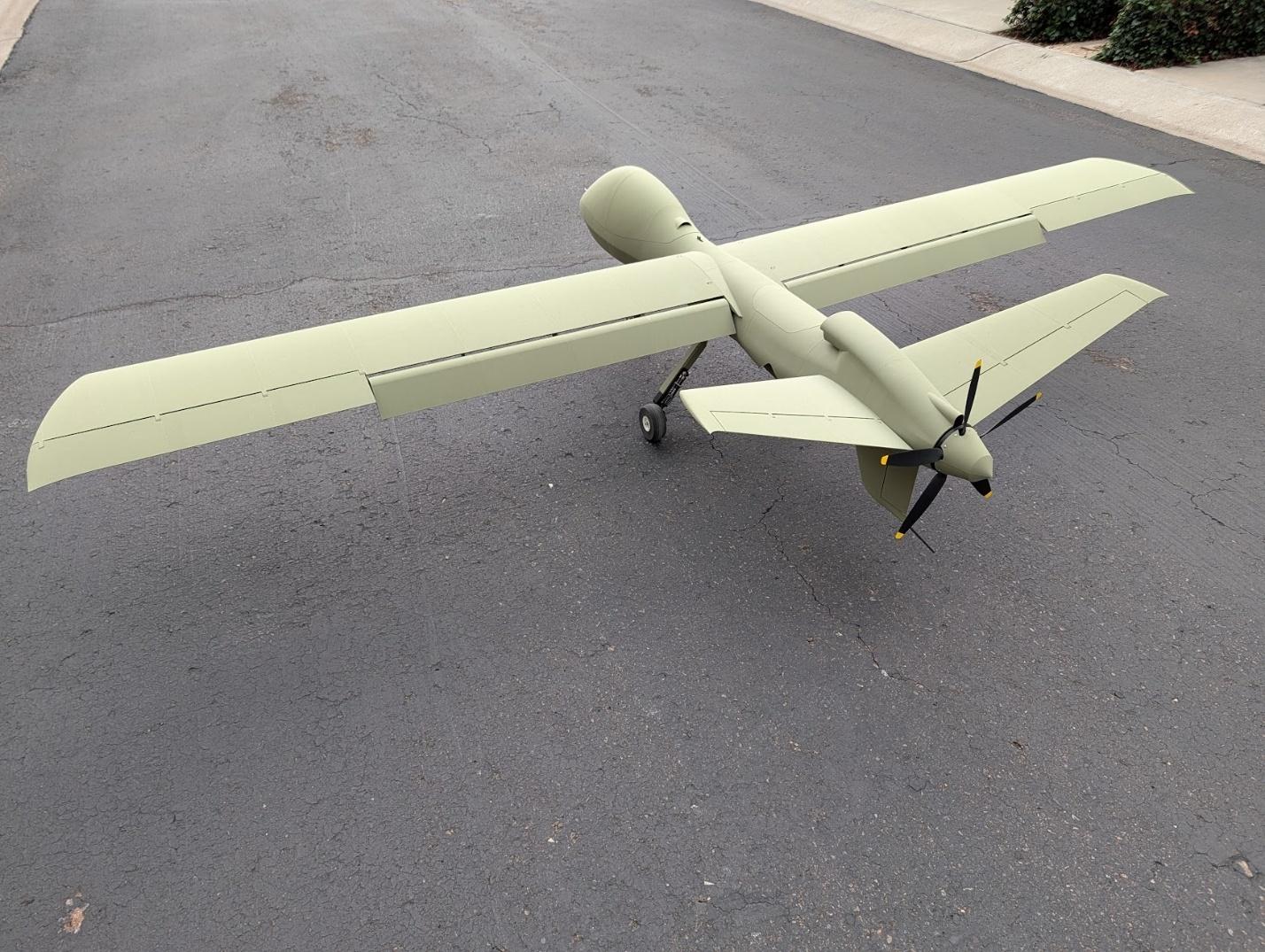
The Mojave is inspired by multi-role unmanned aircraft designed for performance and adaptability in real-world conditions. It's built to fly from rugged environments, achieve impressive flight times, and carry cameras and equipment as desired. It's a capable design that shows how flexible and useful printable model aircraft can be.
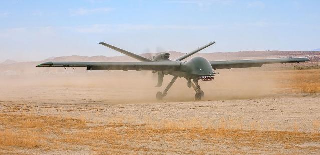
In that spirit, this model can be equipped with an ArduPilot flight controller to enable assisted and autonomous flight features.
Skill meter
Build: This model is quite large but is straightforward to assemble. Heat-set inserts, retractable landing gear, and optional flight controller installation are the most complex features.
Flight: This model has a light wing loading and predictable handling. It is suitable for intermediate pilots.
Specifications
| Spec | Value |
|---|---|
| Wingspan | 3000mm (118") |
| Length | 1650mm (65.0") |
| Wing Area | 87.8dm2 (9.45ft2) |
| Print Weight | 3300-3400g (7.3-7.5lb) |
| Flying Weight | 7700-8200g (17-18lb) |
| Wing Loading | 88-93g/dm2 (29-30oz/ft2) |
| Airfoil | NACA4412 |
Recommended equipment
The following hardware & electronics are required to complete the Mojave. In addition, you'll need some CA glue and activator, epoxy, your R/C transmitter and receiver, and a LiPo battery charger.
Power system & avionics
| Item | Details |
|---|---|
| Motor | BadAss 4530-360kV Motor |
| ESC | BadAss Rebel V2 100A ESC |
| Battery | 6S ~12Ah (two LiPo packs in parallel or single Li-Ion pack) |
| Propeller Blades | FlightLine 16x10 Blades (need 5 blades, 4 per pack) |
| Aileron and Elevator Servos | Hitec HS-85MG (x2) or Hitec D85MG (x2) |
| Flap Servos | Hitec HS-645MG (x2) |
| Rudder & Nosewheel Servos | Hitec HS-65MG (x2) or Hitec HS-70MG (x2) |
| Main Retracts | JP ER-120 – Inside (x2) |
| Nose Retract | JP ER-120 – 100 Degree Inside |
| Retract Controller | JP Tricycle Retract Control Box |
| Shock Absorbers | 140mm Aluminum Shock Absorber (Similar alternatives are available from multiple sources) |
| Shock Oil | 60WT Silicone Shock Oil |
| Short Servo Extensions | 40cm Servo Extensions |
| Medium Servo Extensions | 80cm Servo Extensions |
| Long Servo Extensions | 100cm Servo Extensions |
| Motor Leads | 12AWG Silicone Wire |
| Battery Leads | 10AWG Silicone Wire |
| Pylon Release Servos (Optional) | JX DHV56MG (x2) |
Autopilot equipment (Optional)
| Item | Details |
|---|---|
| Flight Controller | Matek H743-Wing |
| GPS Receiver | Matek M10Q GPS with Compass |
| Airspeed Sensor | Matek Digital Airspeed Sensor |
Carbon fiber
| Tube | Cut Lengths | Qty | Link |
|---|---|---|---|
| 16mm x 14mm x 1000mm Tube | Forward Wing Joiner Sleeves – 500mm – x2 (1000mm tube cut in half is OK) Aft Wing Joiner Sleeves – 420mm – x2 Center Wing Joiner Sleeve – 158mm |
2 | 16mm x 14mm Carbon Tube |
| 14mm x 12mm x 1000mm Tube | Wing Joiner – 1000mm – x2 | 2 | 14mm x 12mm Carbon Tube |
| 12mm x 10mm x 1000mm Tube | Main Struts – 248.5mm – x2 Nose Strut – 205mm |
1 | 12mm x 10mm Carbon Tube |
| 10mm x 8mm x 1000mm Tube | Tail Joiner Sleeves – 80mm – x2 | 1 | 10mm x 8mm Carbon Tube |
| 8mm x 6mm x 1000mm Tube | Wing Tubes – 1000mm – x4 Fuselage Tubes – 1000mm – x2 Fuselage Lower Tube – 350mm Nose Joiners – 100mm – x2 Forward Tail Tubes – 270mm – x2 Aft Tail Tubes – 74mm – x2 Forward Ventral Tube – 52mm Aft Ventral Tube – 152mm |
8 | 8mm x 6mm Carbon Tube |
| 6mm x 4mm x 1000mm Tube | Tail Skid – 150mm | 1 | 6mm x 4mm Carbon Tube |
| 2mm x 1000mm Solid Rod | Aileron Hinges – 578mm – x2 Elevator Hinges – 500mm – x2 Rudder Hinge – 157mm Flap Stiffener – 828mm – x2 |
5 | 2mm Carbon Rod |
Filament
Good filament matters more here than on most prints. The materials below have been tested with our filament and process settings and produce good results. Alternate options are listed as well, though weight and durability may vary.
| Use | Filament | Amount |
|---|---|---|
| LW-PLAAirframe skins — wings, tail and fuselage. | 3DLabPrint PolyLight or ColorFabb LW-PLA or Bambu PLA Aero | ~2,751 g |
| PLAStructure, accessories, and thin-wall airframes. | 3DLabPrint PolyAir or eSun PLA+ or Bambu PLA Tough+ | ~279 g |
| PETG-CF / PETG-GFHigh-load parts. Needs a hardened nozzle — carbon and glass fill are both abrasive. | Bambu PETG-CF or Tinmorry PETG-GF | ~256 g |
| Foaming TPUTires and flexible parts. | 3DLabPrint FlexiLight or ColorFabb VarioShore TPU | ~95 g |
| Alternate material options | ||
| LW-ASA replaces LW-PLAHeat and UV resistant. Needs a heated enclosure and the 0.20mm LW-ASA profiles — see Profiles used by this model. | ColorFabb LW-ASA or Bambu ASA Aero | — |
| PETG replaces PLAHigher heat tolerance. Same process profile — load your slicer's own PETG filament preset. | Bambu PETG Basic or Hatchbox PETG | — |
Hardware
| Item | Part |
|---|---|
| Threaded Inserts | M3 Short Insert (x28, pack contains 100) |
| Motor Mount Threaded Inserts | M4 Short Insert (x4, pack contains 100) |
| Motor Mount Bolts | M4x14 Socket Head (x4) |
| Flap Hinges | M2.5x12 Socket Head (x10) M2.5 Washer (x20) M2.5 Lock Nut (x10) |
| Landing Gear Axles and Joints | M4x30 Countersink (x3) M4x60 Button Head (x3) M4 Washer (x5) M4 Lock Nut (x6) |
| Landing Gear Strut Mounts | M3x20 Socket Head (x2) M3x16 Socket Head (x2) M3 Low Profile Washer (x2, pack contains 100) M3 Lock Nut (x2) |
| Landing Gear Bearings | 684ZZ 4x9x4mm Bearings (x6, pack contains 20) |
| Landing Gear Mount Bolts | M3x12 Countersink (x12) |
| Servo and Hatch Mount Screws | #2x3/8" Tapping (~x80) #2 Washer (~x20) |
| Payload Pod Mount Screws | M3x25 Countersink |
| Ball Link Ends | M2 Ball Linkage (x16, two packs of 10) M2 Lock Nut (x16) |
| Aileron Pushrods | M2 x 95mm Pushrods |
| Elevator Pushrods | M2 x 55mm Pushrods |
| Flap, Rudder and Nose Steering Pushrods | M2 Fully Threaded Rod (cut as necessary) |
| Pylon Mount Screws (Optional) | #4x7/8" Tapping (x6) |
Note: A convenient hardware pack containing all inserts and fasteners is available from Lofted Aero HERE.
Printing thin-wall models
Desktop 3D printers are perfectly capable of producing great-flying R/C models durable enough to withstand hangar rash and general use. However, aircraft designs contain a unique mix of thin surfaces and intricate solid supports that require some practice to print perfectly. Keep the following tips in mind when printing your model.
Slicing the project files
The model download includes .3MF project files for both Bambu Studio and OrcaSlicer – modern, free, and open source slicers with wide support for popular printers and the ability to utilize multiple plates and varying settings within a single project. These project files include print settings tailored to the model as well as filament settings with adjusted temperature and retractions. The provided settings have been tested to suit a wide range of printers – in most cases, no changes should be necessary aside from choosing your printer.
Open the folder for the slicer you're running. The two sets are equivalent and the workflow is the same in both, but each is written in its own slicer's settings dialect, so they aren't interchangeable.
The process and filament presets these projects use are our own. You don't need them to print – the project files already carry the settings – but importing them once from the Print Settings page keeps them in your slicer for future projects, and that page explains what each one is for.
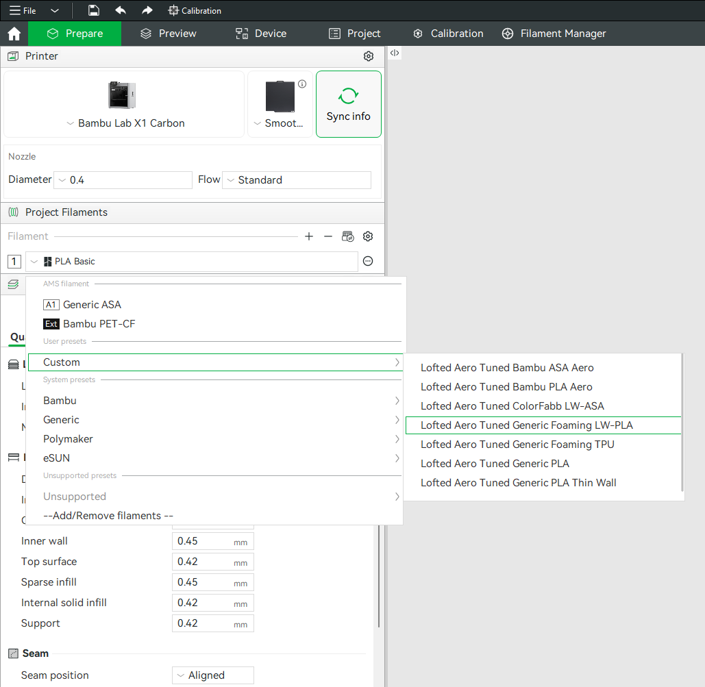
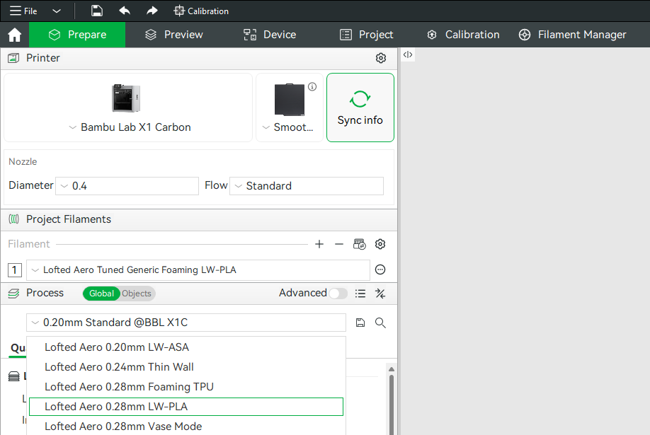
Generic example screenshots
These happen to show the LW-PLA profiles being picked. The profiles this model uses are listed just below.
Profiles used by this model
| Project file | Process profile | Filament profile |
|---|---|---|
| Fuselage · Optional Pylons · Tail · Wings | Lofted Aero 0.28mm LW-PLABambu Studio OrcaSlicer | Lofted Aero Tuned Generic Foaming LW-PLABambu Studio OrcaSlicer |
| TPU Parts | Lofted Aero 0.28mm Foaming TPUBambu Studio OrcaSlicer | Lofted Aero Tuned Generic Foaming TPUBambu Studio OrcaSlicer |
| Mouth Graphic | Your slicer's own 0.08mm High Quality |
Lofted Aero Tuned Generic PLABambu Studio OrcaSlicer |
| PETG Parts | Your slicer's own 0.20mm Standard |
Your slicer's own Bambu PETG-CF |
| PLA Parts | Your slicer's own 0.20mm Standard |
Lofted Aero Tuned Generic PLABambu Studio OrcaSlicer |
Hardware parts like latches, trays, mounts and gear ride your slicer's own stock profile, which is already matched to your printer.
Printing the airframe in LW-ASA instead? Substitute Lofted Aero 0.20mm LW-ASA for the LW-PLA process profile, with either the Bambu ASA Aero or ColorFabb LW-ASA filament profile from the Print Settings page. LW-ASA needs a heated enclosure. Everything else in the table is unchanged.
Modifiers and per-object settings
Both slicers allow per-object modifications to slicing settings, and this method is used heavily in the provided .3MF files. Where a part needs extra perimeters, different infill, or a relocated seam, that's applied as a per-object modifier on top of the profile rather than as a separate profile. Some of these modifiers apply to every part in a group, and the print table below lists them alongside the profile. When making settings changes, be mindful of these per-object settings as well as any other modifiers applied to each part. Switch the Process panel from Global to Objects to see every part in the project, the settings overridden on it, and any modifier volumes attached to it.
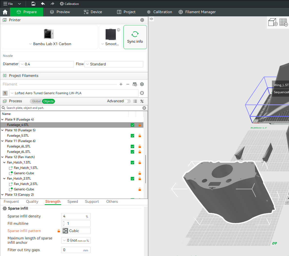
(example screenshot shown – may not represent this model)
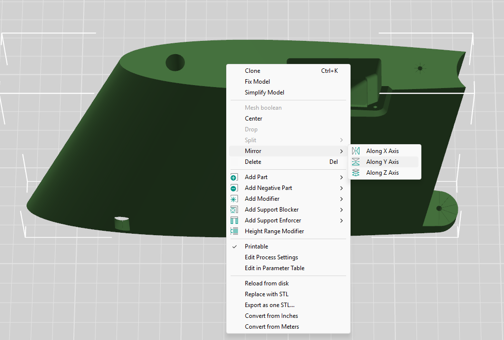
Mirrored parts
You'll notice that the included STL files often contain parts for only one side of symmetrical components like wings, tail surfaces, and landing gear. Don't worry – you can simply mirror these parts in your slicer to produce the other side. When using the included .3MF project files, this mirroring has already been done.
Other printing options
If you'd rather configure and slice the STL files yourself with the software and method of your choice, refer to the print table below for the profile and modifiers applied to each part.
A few things to keep in mind:
- Retraction should be just enough to prevent stringing between features
- Extra length on restart should be just enough to prevent sparse extrusion at layer start
- Extrusion ratio should be adjusted until print weight equals the suggested part weight
Print table
Reference print profiles, per-part modifiers, and weights for each part.
| Part | Weight | Print Profile | Modifiers |
|---|---|---|---|
| LW-PLA Parts | |||
| Wing L1 and R1 | 88g each | Lofted Aero 0.28mm LW-PLA0.28mm Height 0.42mm Extrusion Width 1 Perimeter 3 Top / 3 Bottom Layers 2D Lattice @ 4% Back Seam Classic Wall Generator 238°C Nozzle / 56°C BedModifiers on every part in this group:2 Perimeters 2.5% Fill Nearest Seam |
|
| Wing L2 and R2 | 87g each | ||
| Wing L3 and R3 | 84g each | ||
| Wing L4 and R4 | 73g each | ||
| Wing L5 and R5 | 64g each | ||
| Wing L6 and R6 | 55g each | — | |
| Wing L7 and R7 | 48g each |
| |
| Wing L8 and R8 | 3g each | ||
| Flap L1 and R1 | 4g each |
| |
| Flap L2 and R2 | 21g each | ||
| Flap L3 and R3 | 22g each | ||
| Flap L4 and R4 | 22g each | ||
| Flap L5 and R5 | 22g each | ||
| Aileron L1 and R1 | 20g each |
| |
| Aileron L2 and R2 | 19g each | — | |
| Aileron L3 and R3 | 19g each | ||
| Aileron L4 and R4 | 4g each | ||
| Tail L1 and R1 | 39g each | ||
| Tail L2 and R2 | 26g each | ||
| Tail L3 and R3 | 17g each | ||
| Tail L4 and R4 | 5g each | ||
| Elevator L1 and R1 | 2g each | ||
| Elevator L2 and R2 | 15g each | ||
| Elevator L3 and R3 | 13g each |
| |
| Elevator L4 and R4 | 10g each | — | |
| Ventral Tail 1 | 21g | ||
| Ventral Tail 2 | 4g | ||
| Rudder 1 | 3g |
| |
| Rudder 2 | 10g |
| |
| Nose 1 | 32g | Lofted Aero 0.28mm LW-PLA0.28mm Height 0.42mm Extrusion Width 1 Perimeter 3 Top / 3 Bottom Layers 2D Lattice @ 4% Back Seam Classic Wall Generator 238°C Nozzle / 56°C BedModifiers on every part in this group:2 Perimeters 3% Fill Cubic Infill |
|
| Nose 2 | 44g | — | |
| Fuselage 1 | 36g | ||
| Fuselage 2 | 46g | ||
| Fuselage 3 | 93g | ||
| Fuselage 4 | 84g | ||
| Fuselage 5 | 100g | ||
| Fuselage 6 | 132g | ||
| Fuselage 7 | 112g | ||
| Fuselage 8 | 150g | ||
| Fuselage 9 | 92g | ||
| Canopy 1 | 20g |
| |
| Canopy 2 | 49g | — | |
| Canopy 3 | 53g | ||
| Canopy 4 | 18g | ||
| Hatch 1 | 17g |
| |
| Hatch 2 | 6g | — | |
| Gear Faring L1 and R1 | 4g each | ||
| Gear Fairing L2 and R2 | 4g each | ||
| Spinner | 13g |
| |
| Pylons L and R (Optional) | 18g each |
| |
| Total LW-PLA Parts | 2751g | ||
| PLA Parts | |||
| Battery Tray | 46g | Your slicer's own 0.20mm Standard0.20mm Height 0.42mm Extrusion Width 2 Perimeters 5 Top / 3 Bottom Layers 15% Infill (Grid in Bambu Studio, Cross Hatch in OrcaSlicer) Aligned Seam Classic Wall Generator 210°C Nozzle / 60°C Bed |
— |
| Nose Screw Holder (x4) | 1g each | ||
| Wing Spar Guide (L and R) | 12g | ||
| Wing Joiner Stopper (x2) | 4g each | ||
| 8mm Spar Guide (x4) | 2g each | ||
| Canopy Latch | 4g |
| |
| Hatch Latch | 4g | ||
| Main Gear Mount | 49g | — | |
| Nose Gear Mount | 25g | ||
| Bolt Latch Tab (x9) | 18g total |
| |
| Bolt Latch Receptacle (x9) | 26g total |
| |
| HS-645MG Mount (x2) | 5g each |
| |
| HS-645MG Mount Cover (L and R) | 12g each | ||
| D85MG Mount (x4) | 2g each | ||
| D85MG Mount Cover (x2 L and x2 R) | 4g each | ||
| Servo Receptacle 1x1 (x3, Optional) | 2g each | — | |
| Servo Receptacle 3x1 (x2, Optional) | 5g each | ||
| Total PLA Parts | 279g | ||
| TPU Parts | |||
| Nose Tire | 19g | Lofted Aero 0.28mm Foaming TPU0.28mm Height 0.42mm Extrusion Width 5 Perimeters 8 Top / 8 Bottom Layers Gyroid @ 15% Nearest Seam Arachne Wall Generator 240°C Nozzle / 25°C Bed |
|
| Main Tire (x2) | 38g each | — | |
| Total TPU Parts | 95g | ||
| PETG-CF Parts | |||
| Propeller Hub | 60g | Your slicer's own 0.20mm Standard0.20mm Height 0.42mm Extrusion Width 2 Perimeters 5 Top / 3 Bottom Layers 15% Infill (Grid in Bambu Studio, Cross Hatch in OrcaSlicer) Aligned Seam Classic Wall Generator 255°C Nozzle / 70°C Bed |
|
| Propeller Hub Plate | 6g |
| |
| Motor Mount | 66g |
| |
| Main Gear Arm (L and R) | 18g each |
| |
| Main Gear Joint (L and R) | 16g each | ||
| Main Gear Strut Mount (L and R) | 4g each | — | |
| Strut Reinforcement (x3) | 2.6g each |
| |
| Main Gear Spacer Ball (x2) | 1g total |
| |
| Nose Gear Fork | 23g |
| |
| Nose Gear Joint | 16g |
| |
| Total PETG-CF Parts | 256g | ||
Joining parts
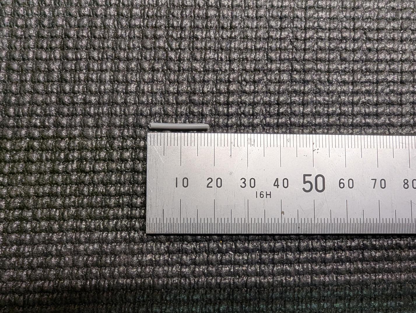
Unless otherwise specified, medium CA and activator are recommended for joining printed parts. In addition, many joints use ~18mm lengths of 1.75mm PLA filament for alignment. Preparing a handful of these ahead of time can help speed up the build.
Wing assembly
-
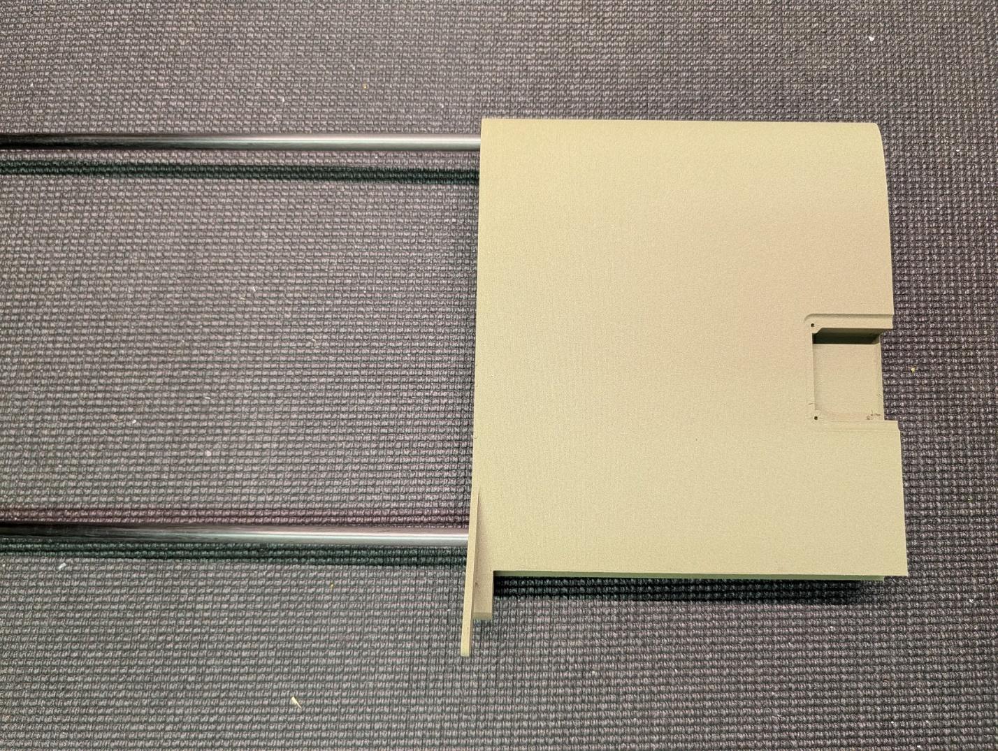
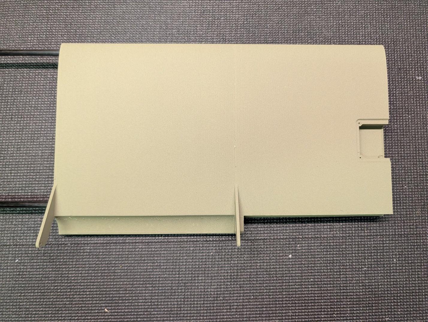
Slide two 8mm x 6mm x 1000mm carbon tubes into wing section 5 and secure with glue.
-
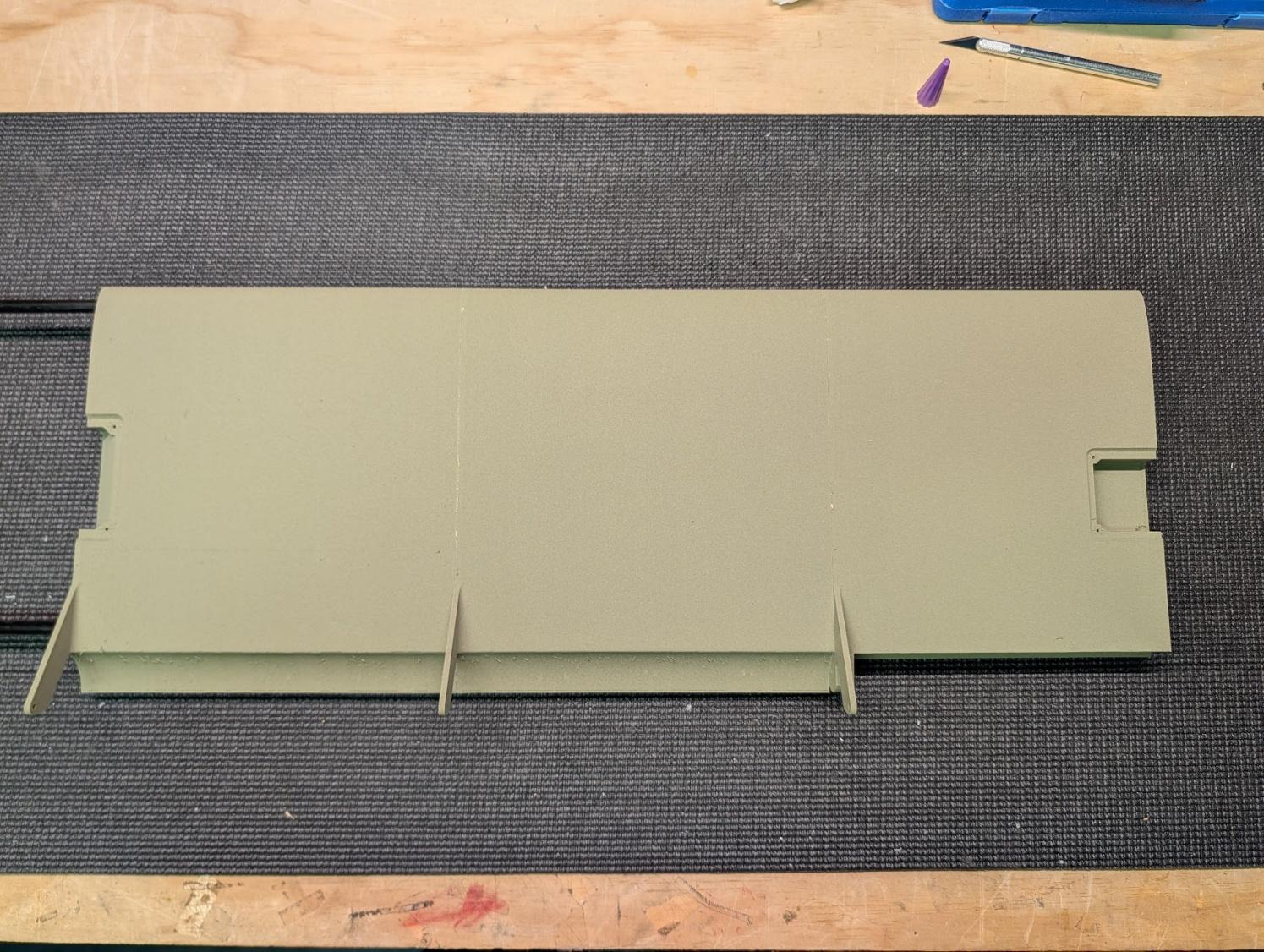
Slide wing section 4 onto the tubes and glue it to section 5 with medium CA. Use a slower curing adhesive such as UHU or epoxy on the carbon tubes themselves to prevent setting before the parts are fully joined.
-
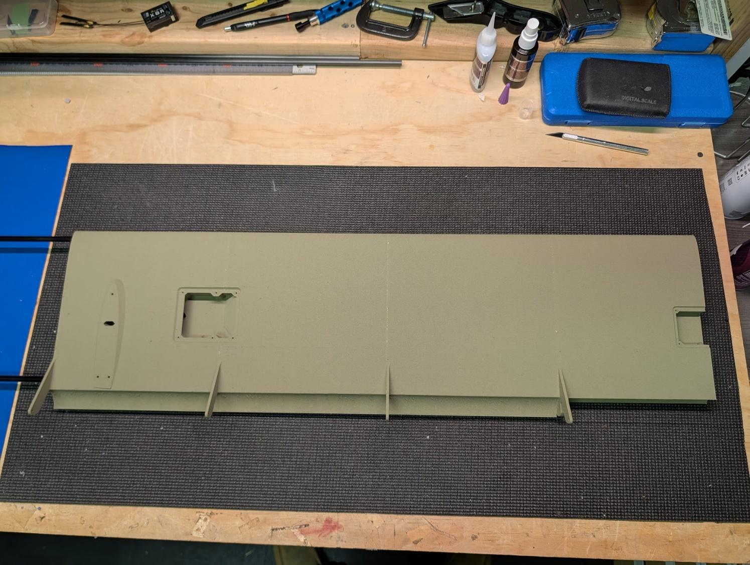
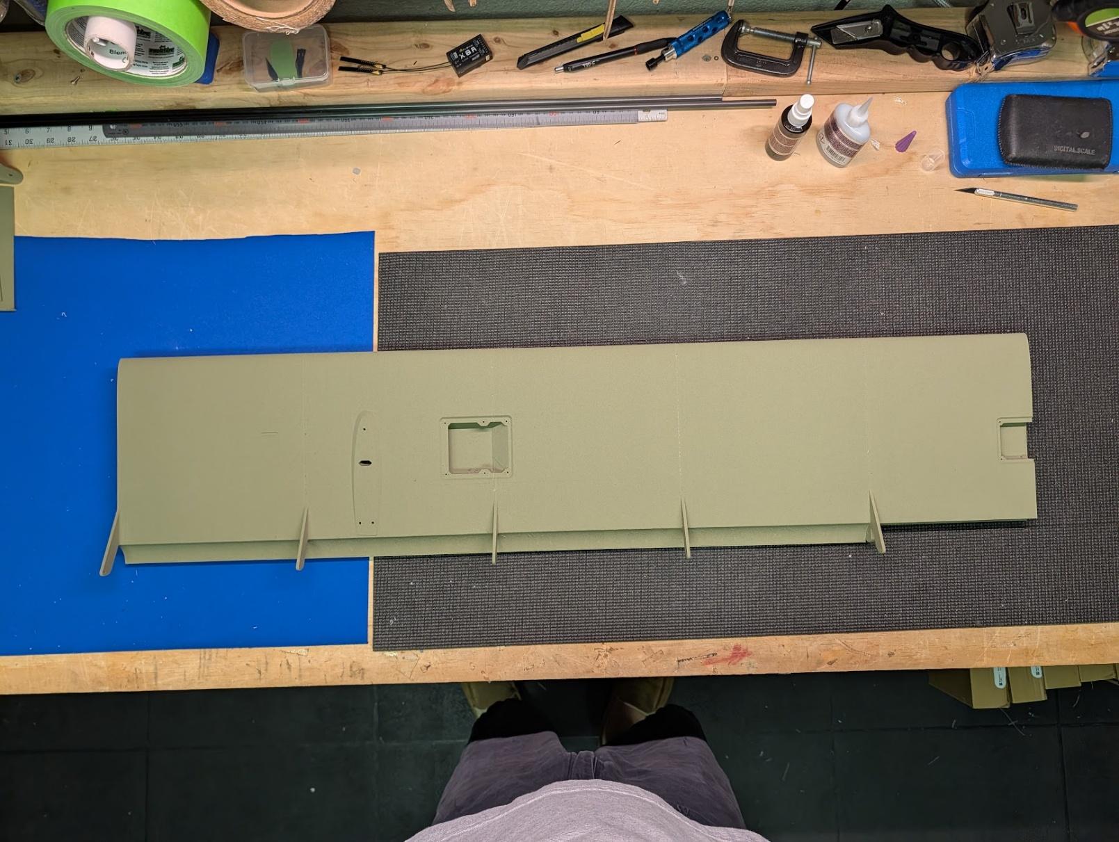
Repeat with wing sections 3, 2, and 1.
-
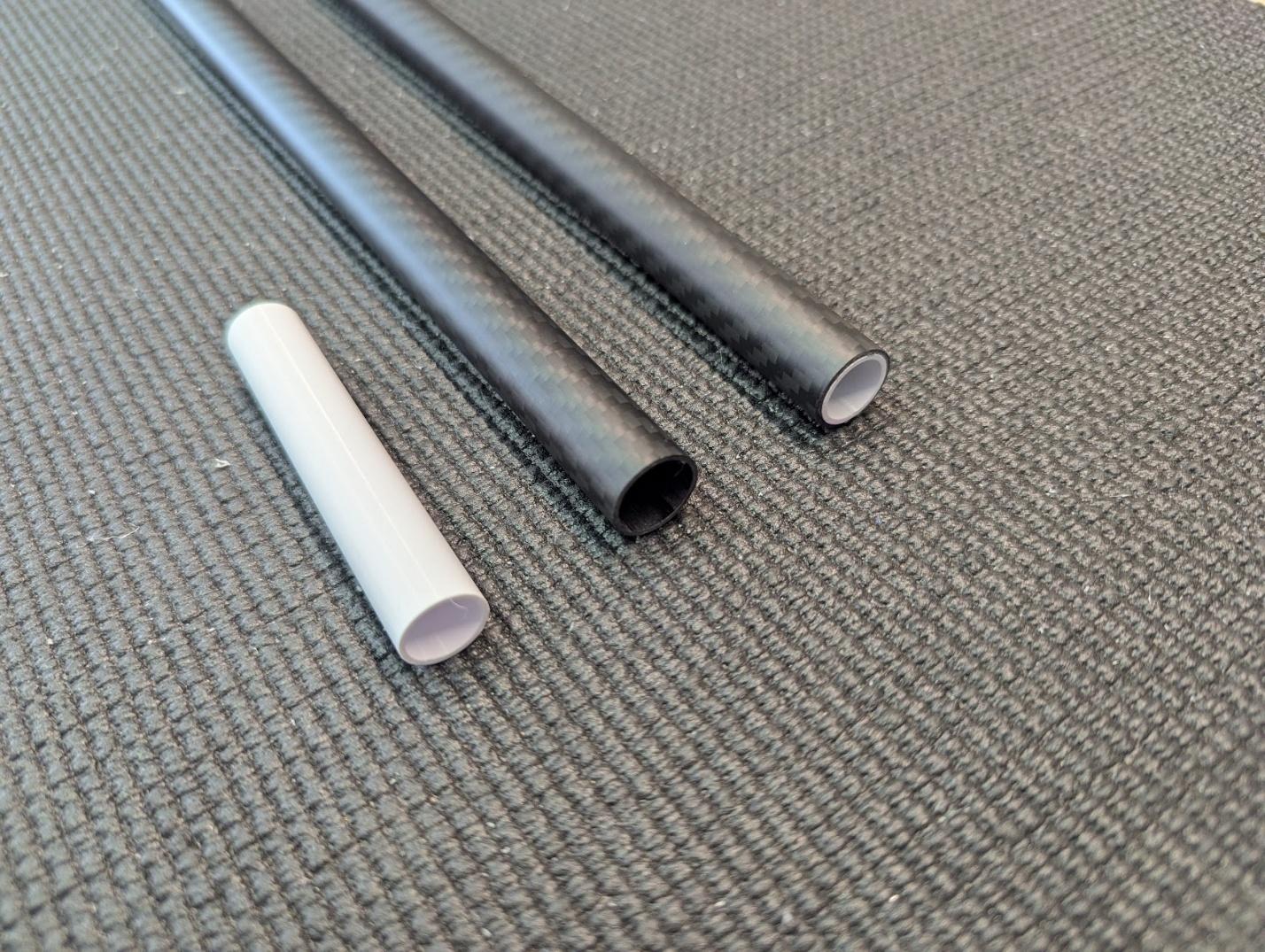
Prepare the 16mm spar joiner sleeves. Cut a 1000mm tube in half to form the forward joiner sleeves. Cut a second 1000mm tube into two 420mm lengths to form the aft joiner sleeves, saving the remaining short length to use for the fuselage in a later step.
-
Glue the printed spacers into the outboard end of the forward joiner sleeves. These ensure that the joiner itself sits centered in the wing. The shorter aft sleeves do not need them.
-
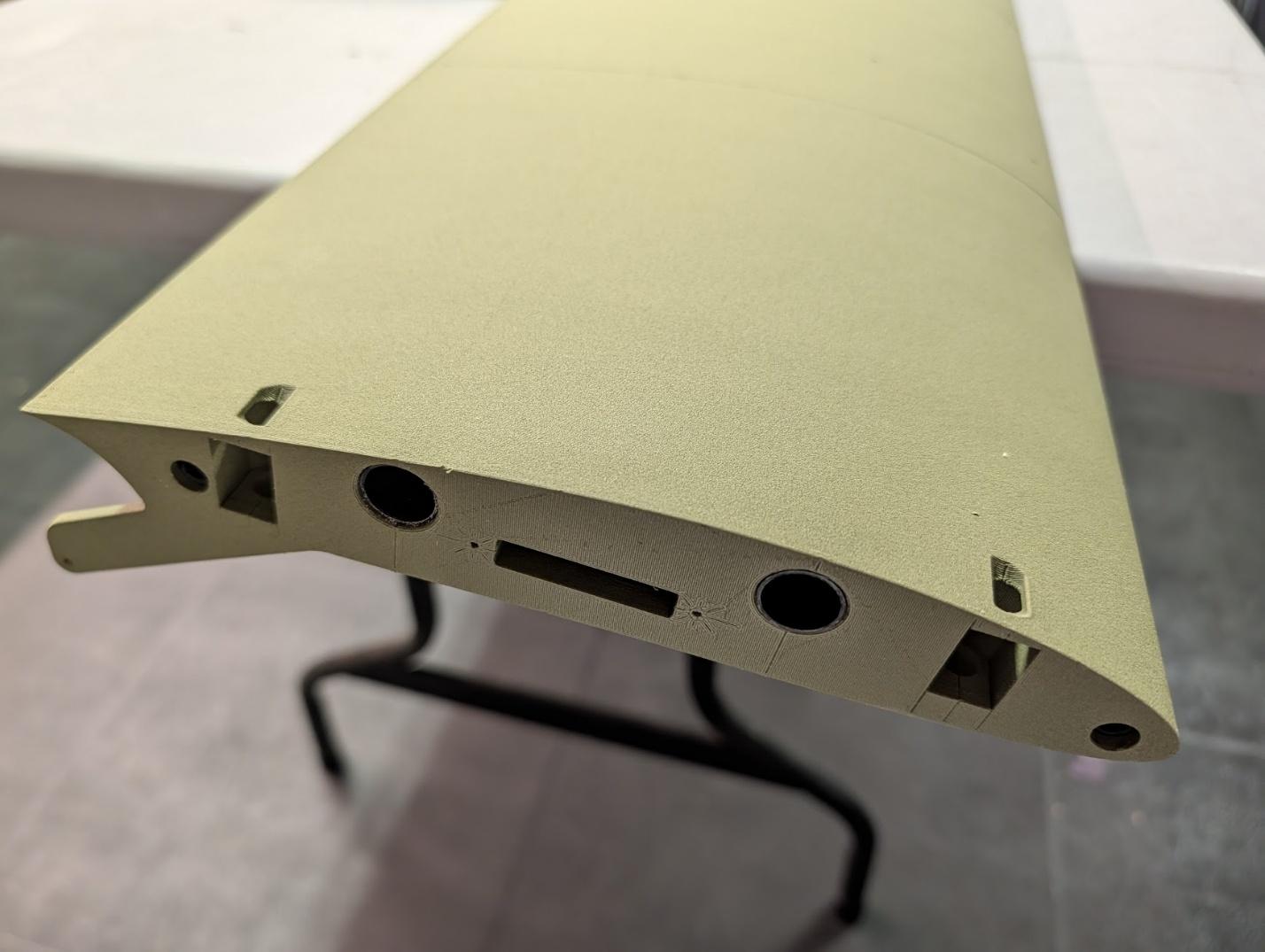
Glue the joiner sleeves into the wings with epoxy, being careful not to get any glue inside the tubes. It is easiest to perform this step before assembling and installing the wingtips.
-
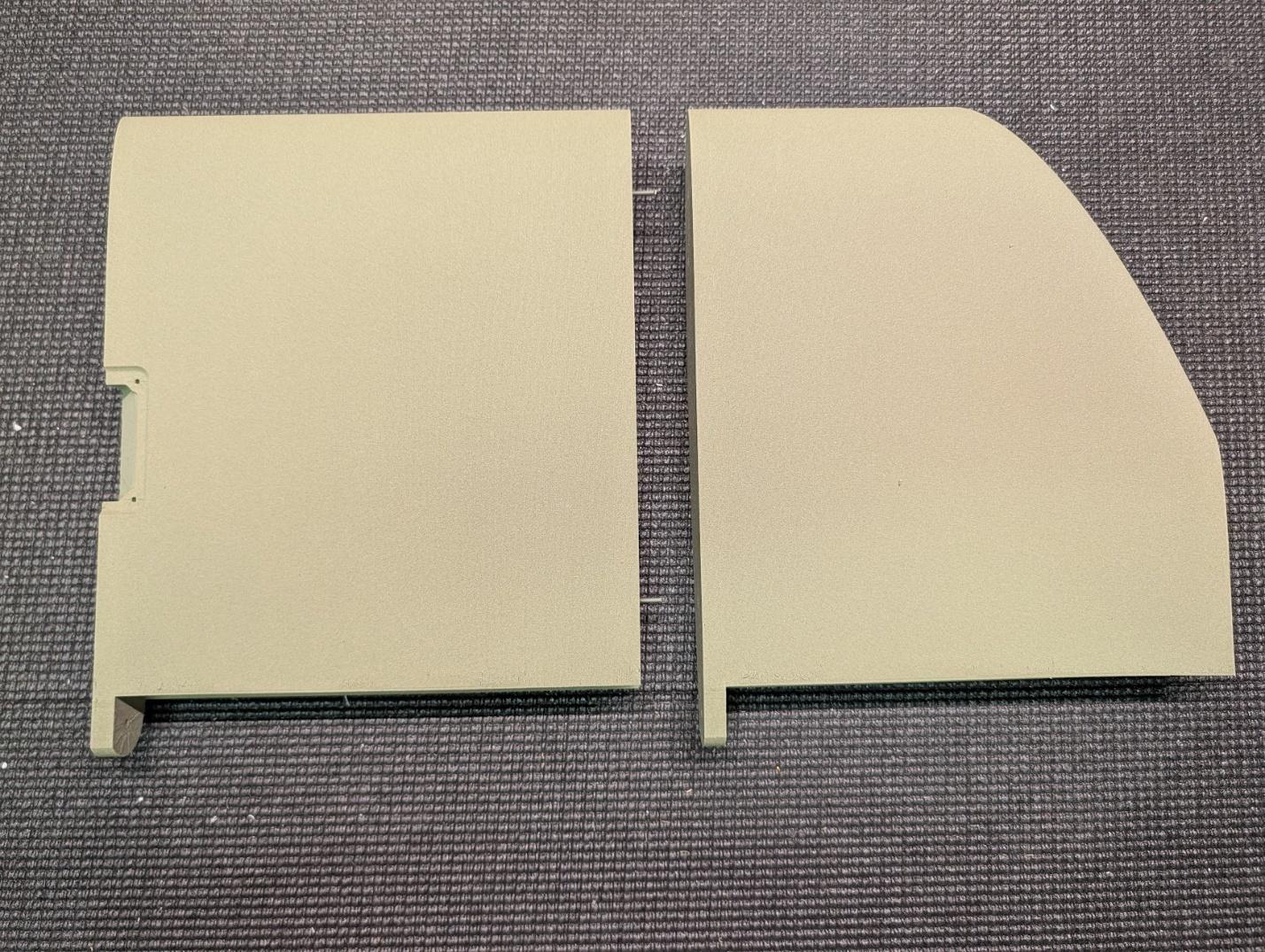
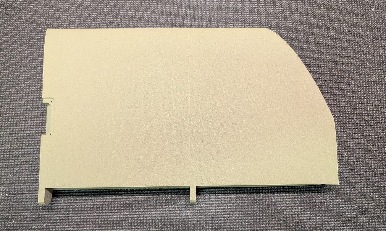
Using some filament guide pins, join wing sections 6 and 7.
-
Similarly, add section 8 to the tip.

-
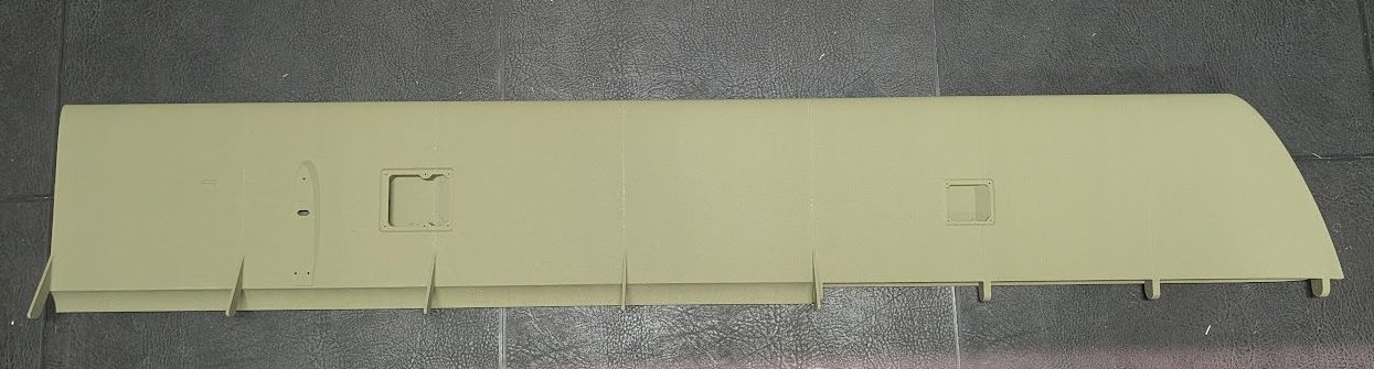
Again using filament guide pins, join the section 1-5 assemblies with the section 6-8 assemblies.
-
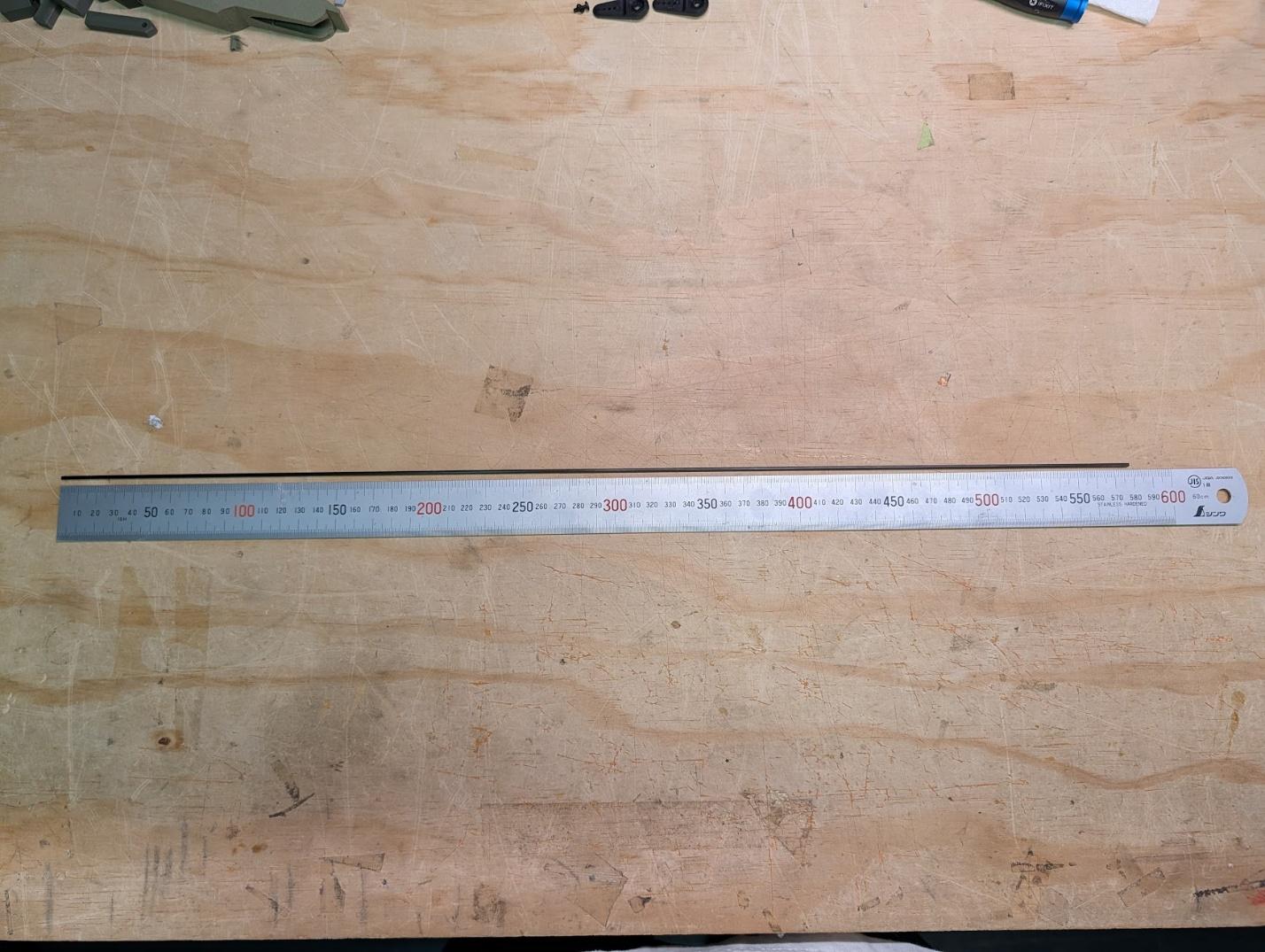
Cut 578mm lengths of 2mm carbon rod for the aileron hinges.
-
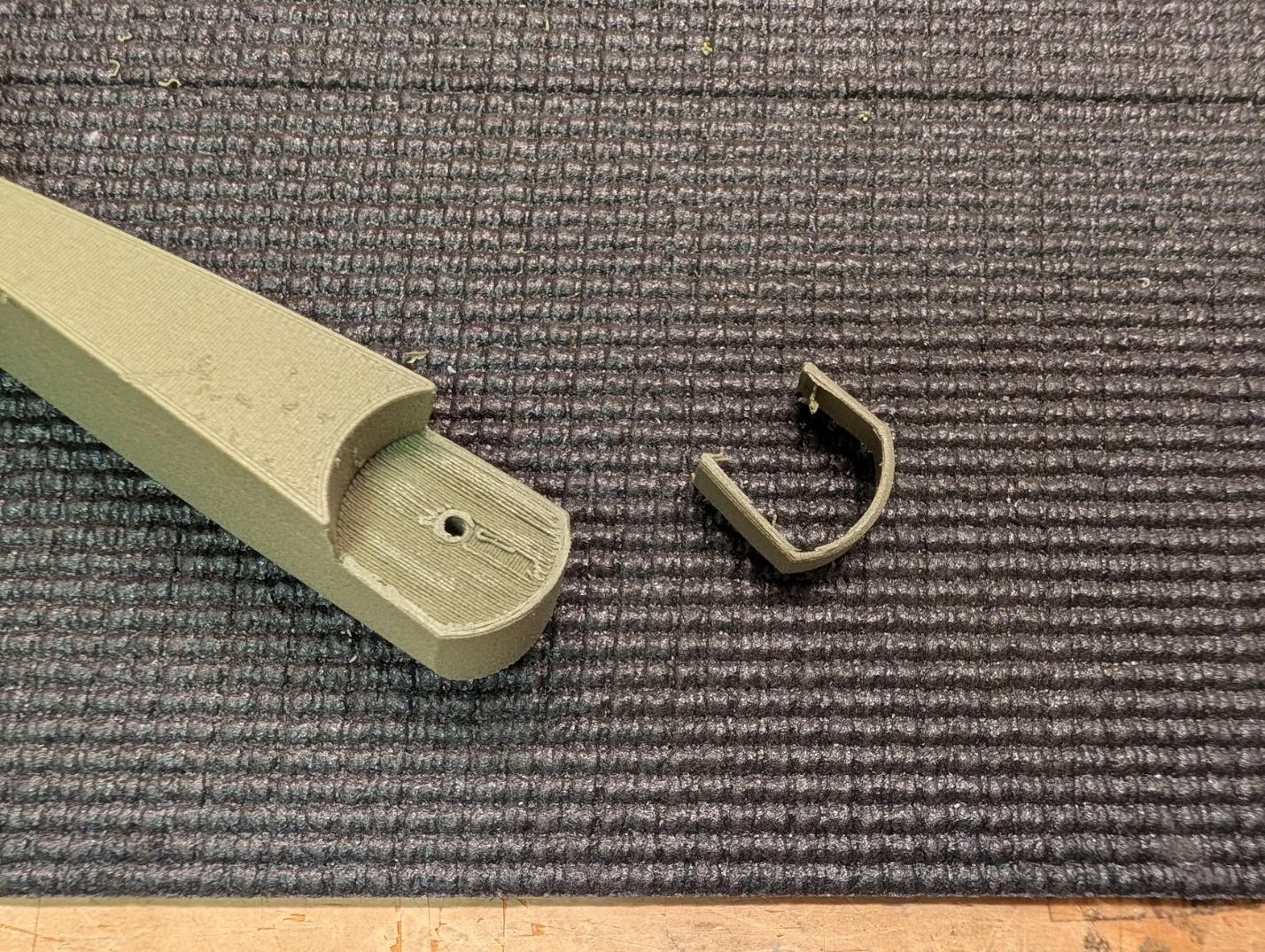
Trim the support material from the aileron tip sections.
-
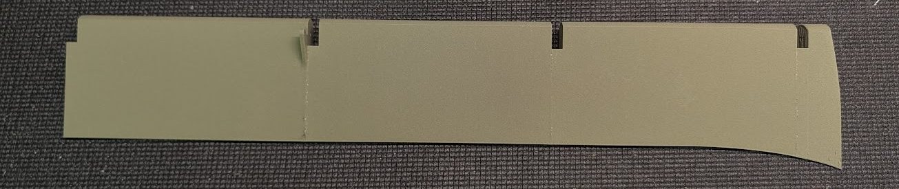
Glue the four sections of the ailerons together, using the rod for alignment if desired. Be careful not to get any glue on the carbon hinge rod.
-
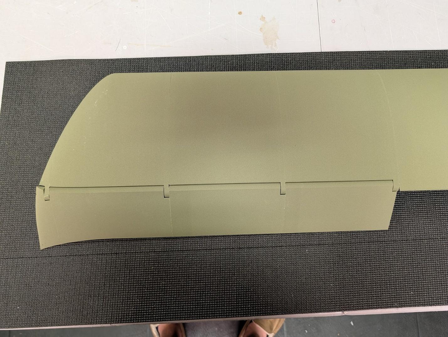
Install the ailerons using the carbon fiber hinge rods.
-
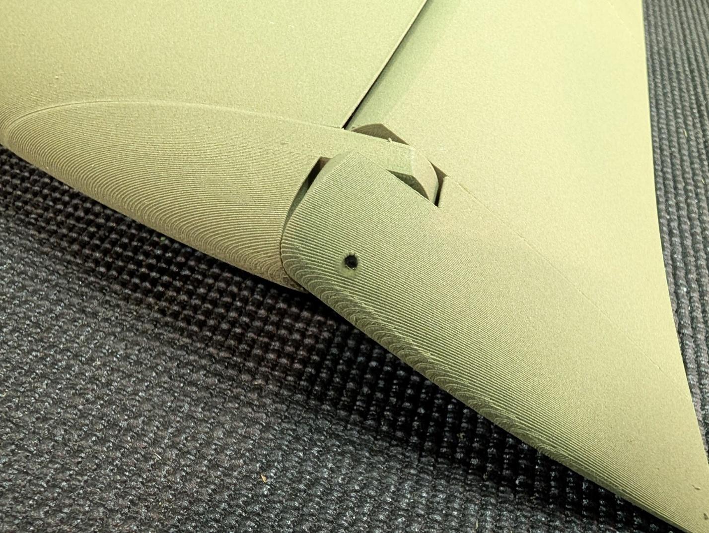
Secure the hinge rods with a drop of CA at the tip.
-
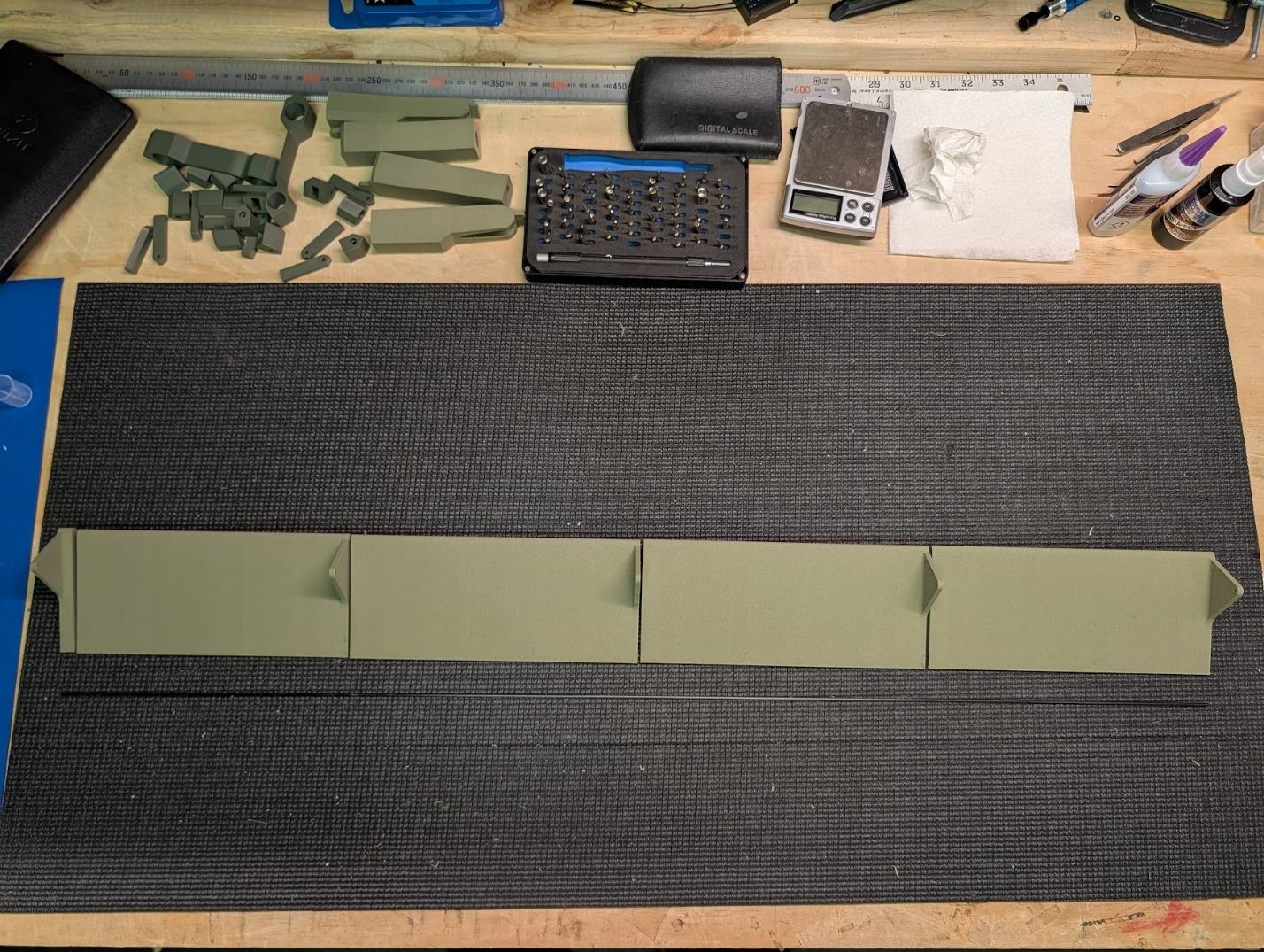
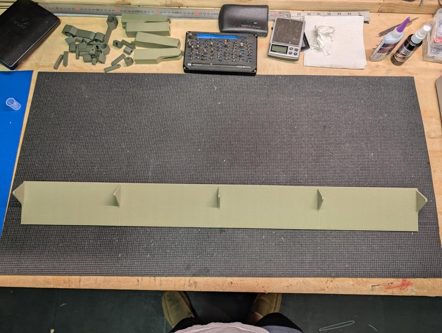
Cut 828mm lengths of 2mm carbon rod to act as stiffeners for the flap sections.
-
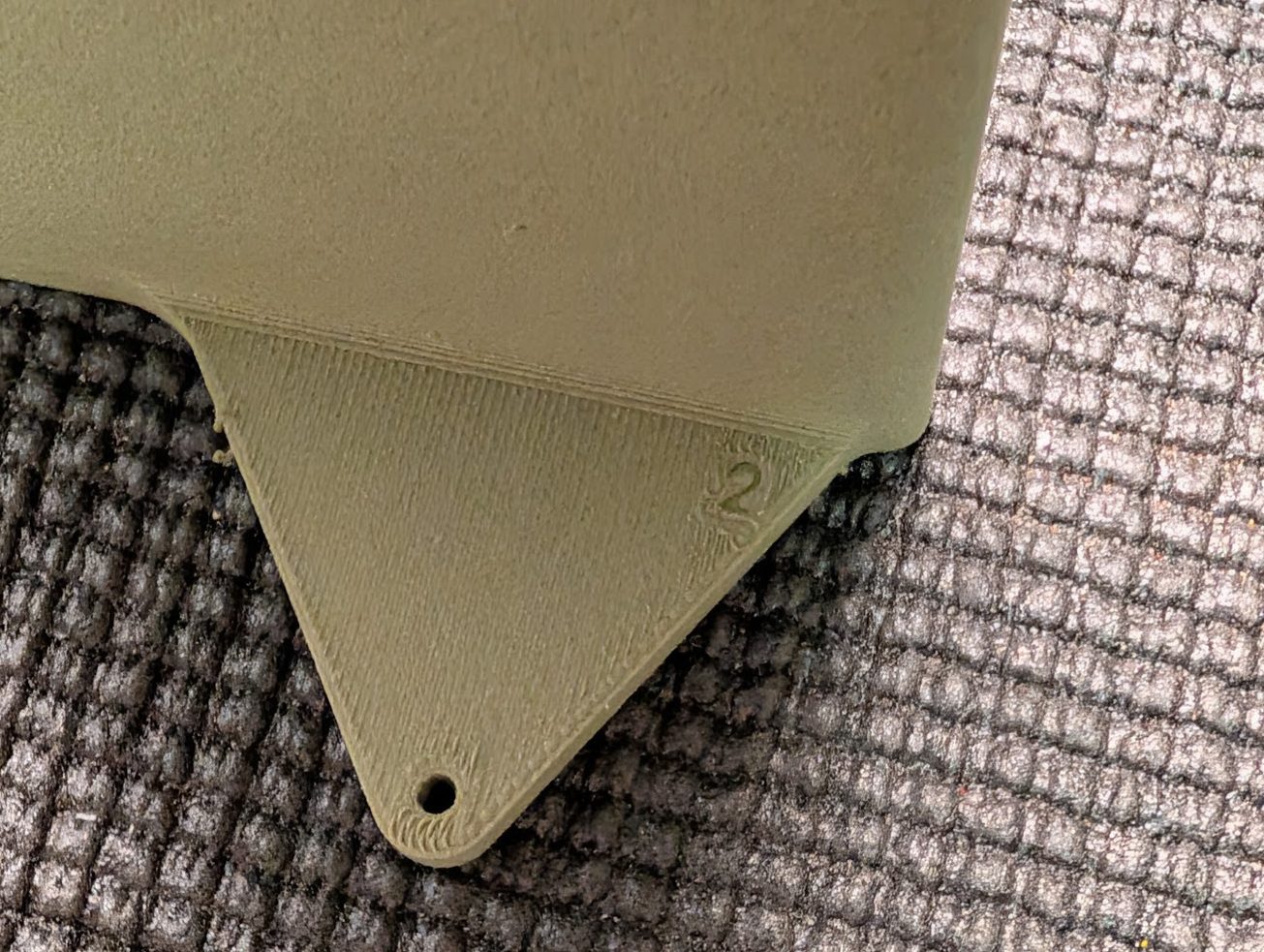
Ensure the sections are in the right order. Since the sections are visually very similar, they're embossed with identifying numbers.
-
Once satisfied, glue the flap sections together including the carbon stiffener rod.
-
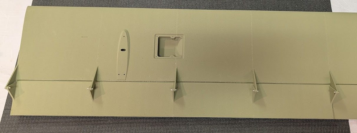
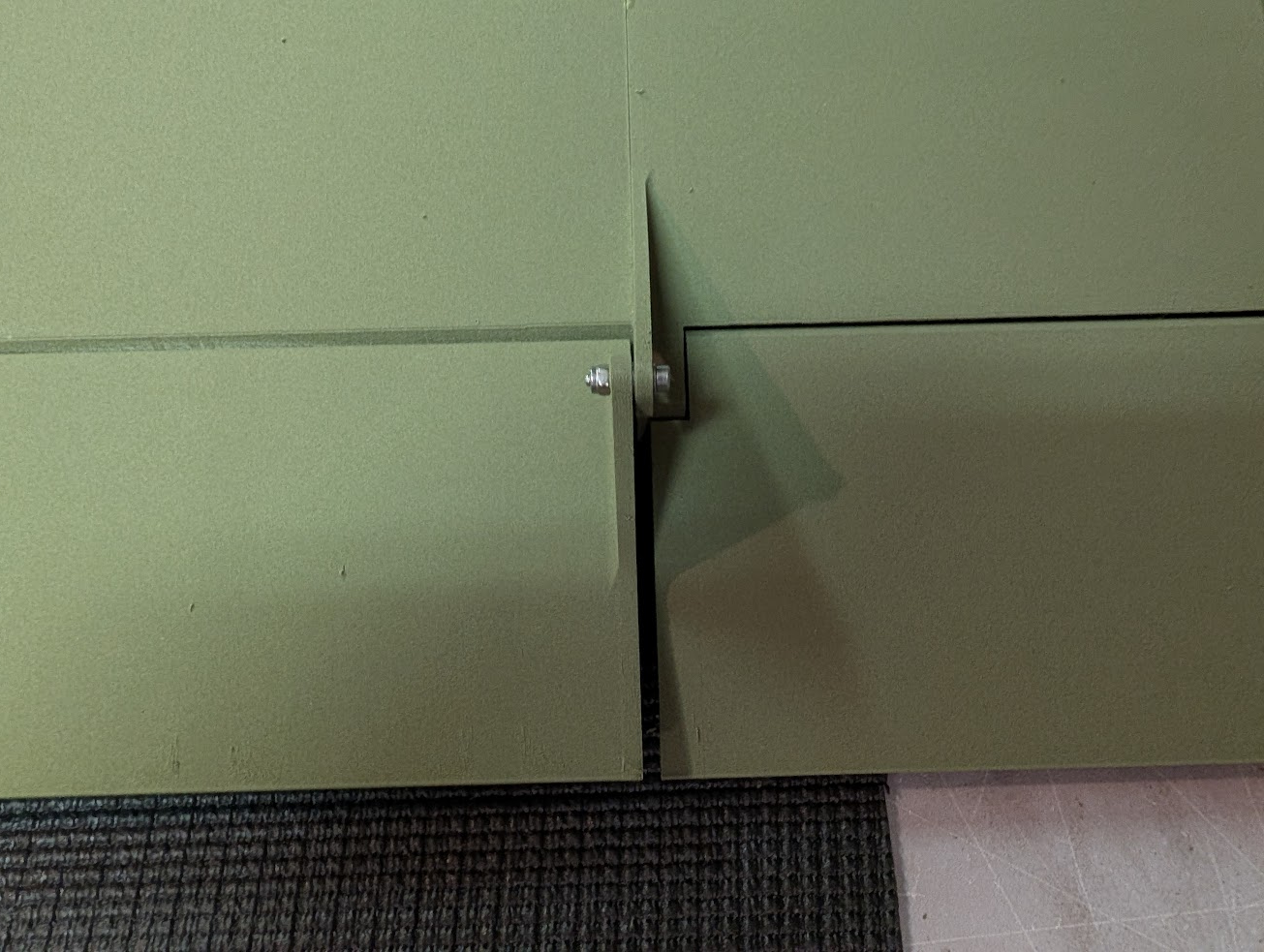
Hinge the flaps to the wing using M2.5 x 10mm screws, washers, and locknuts. Fully tighten each screw one at a time, then loosen until the surface can rotate without resistance or slop.
-
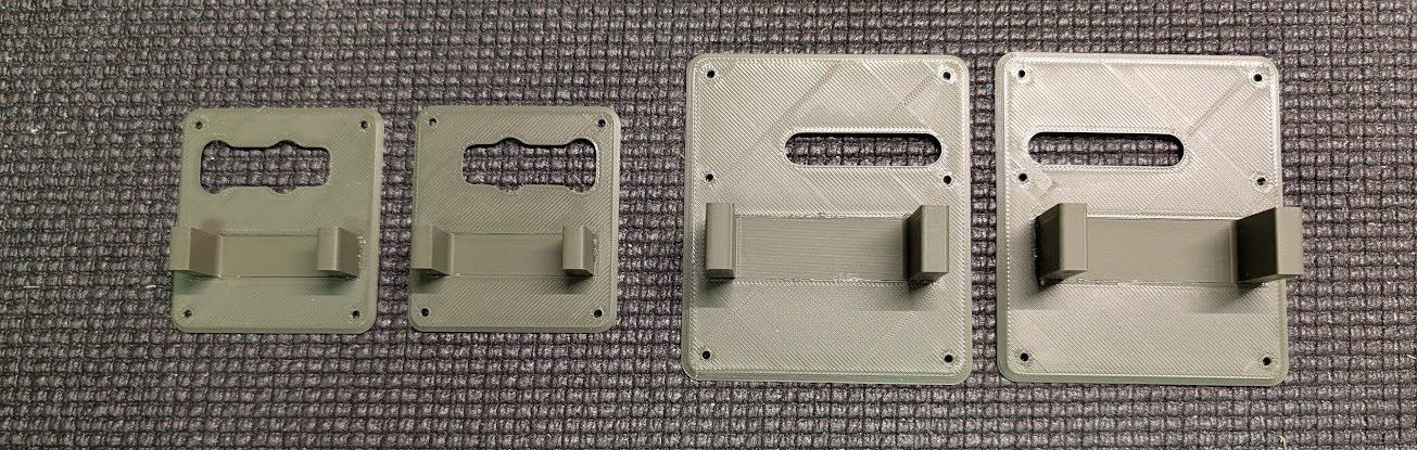
Prepare the wing servo holders by gluing the mount components to the covers. Orientation of the mounts doesn't matter – the parts are symmetrical.
-
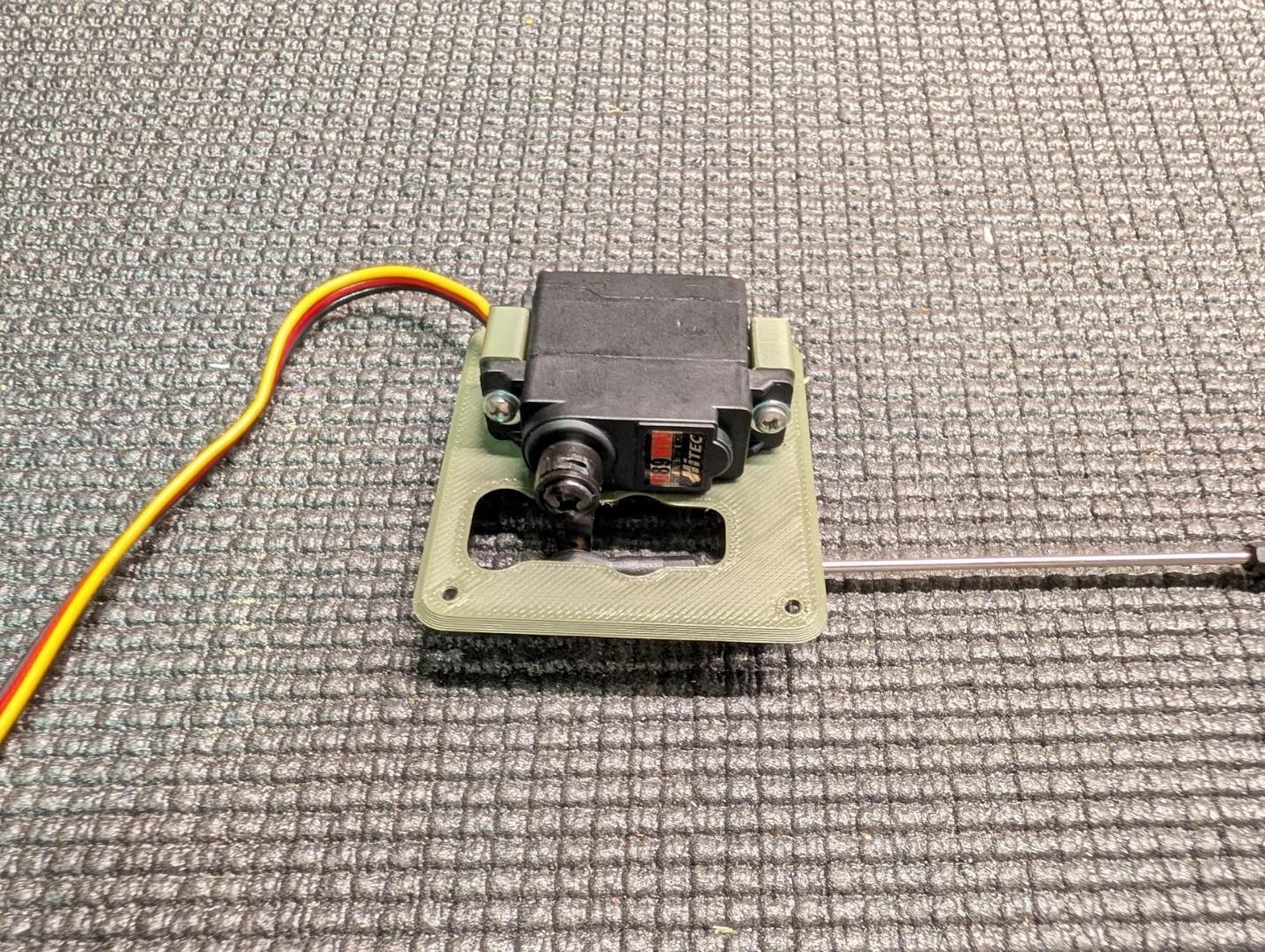
Center the aileron servos and fasten to the mounts using #2 x 3/8" self-tapping screws or the screws included with the servos.
-
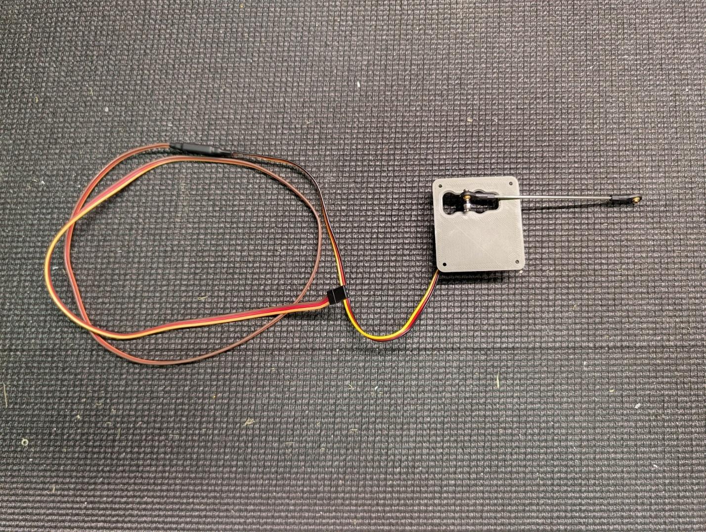
Fit servo extensions as long as necessary for the servo lead to reach the wing root.
-
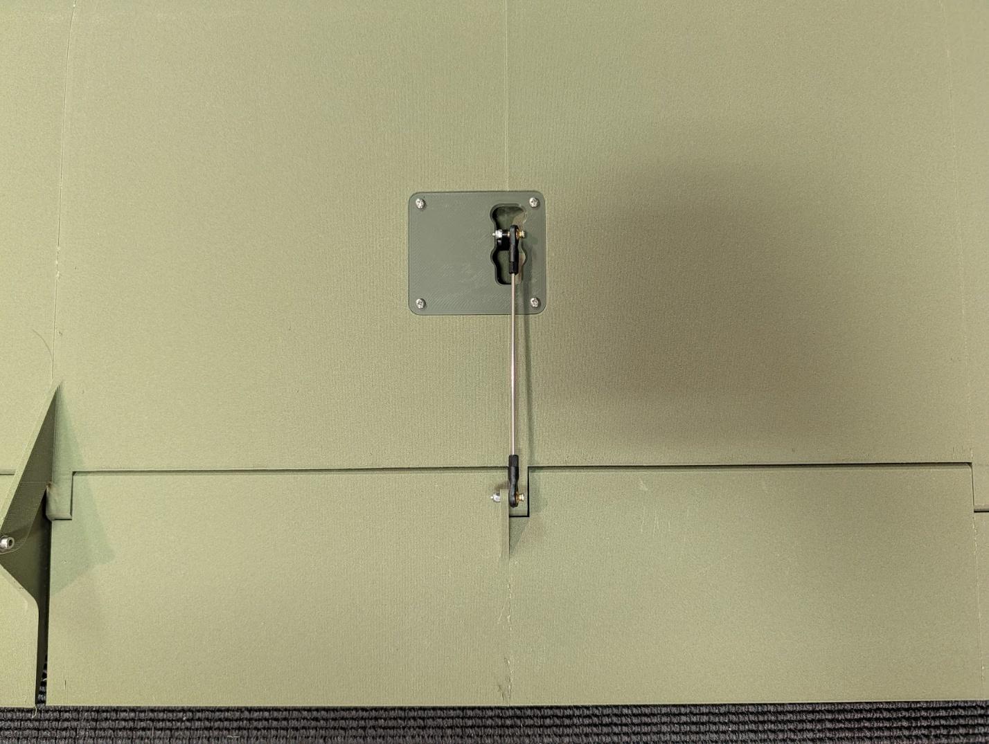
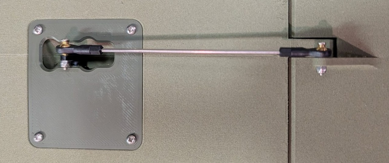
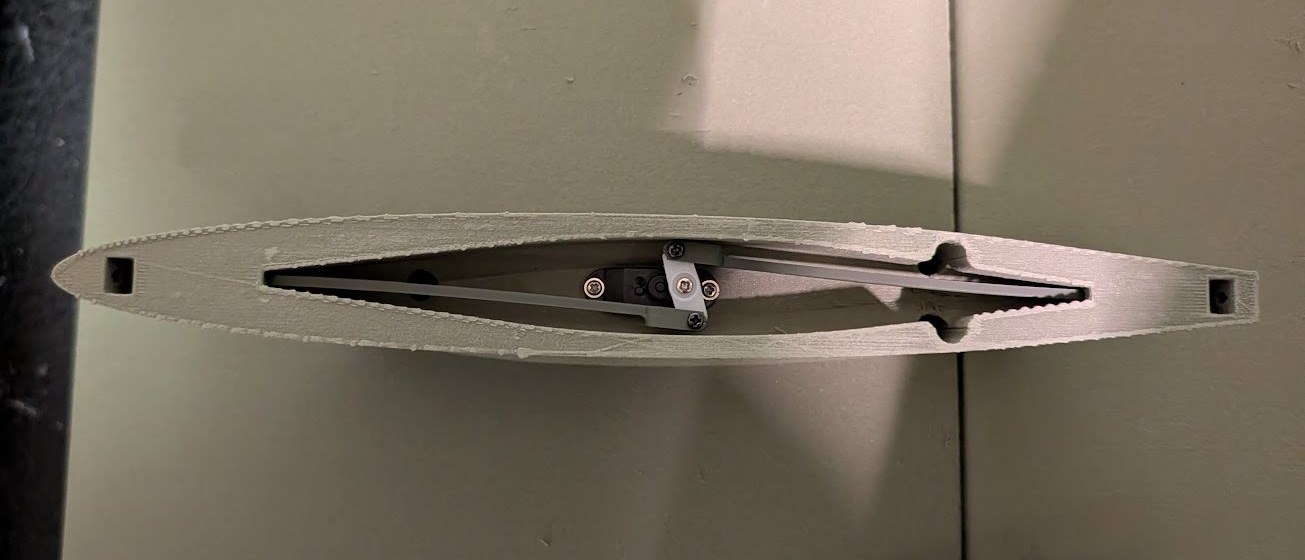
Install the aileron servos using more #2 x 3/8" screws to secure the mount covers to the wing. Assemble and connect pushrods using M2 threaded rods and ball links (as desired).
-
Center the flap servos and secure to the mounts with more #2 self-tapping screws.
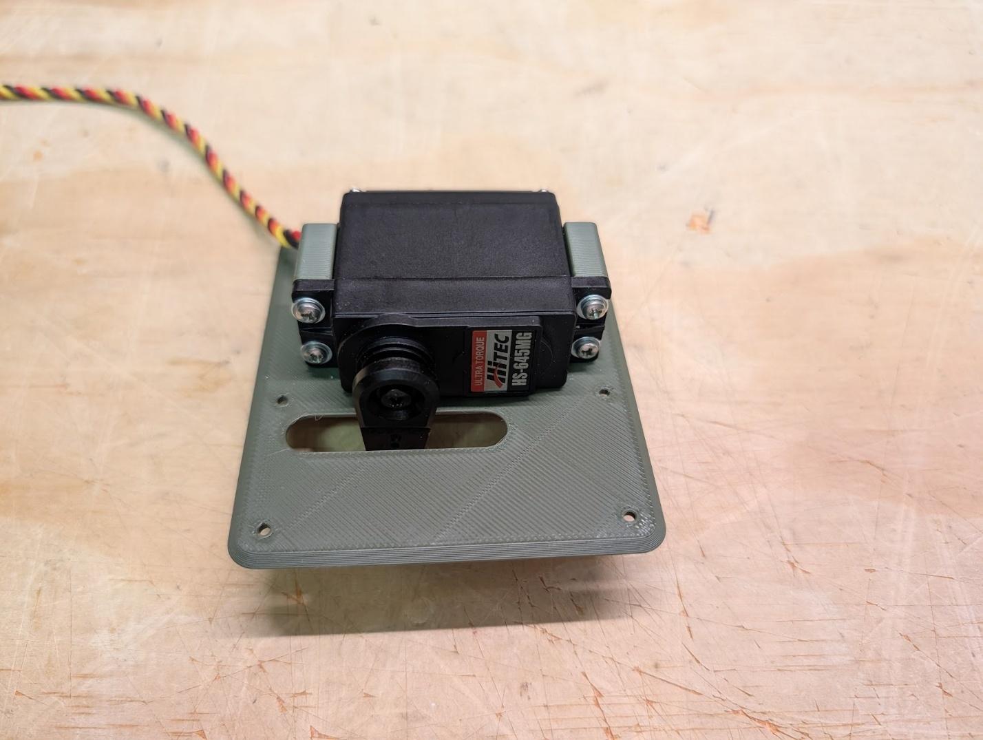
-
Mount the flap servo assemblies to the wing and assemble pushrods as shown. Ensure that the servo arm is forward of neutral when the flap is in the retracted position – 1700 to 1800uS is a good starting PWM value for this.
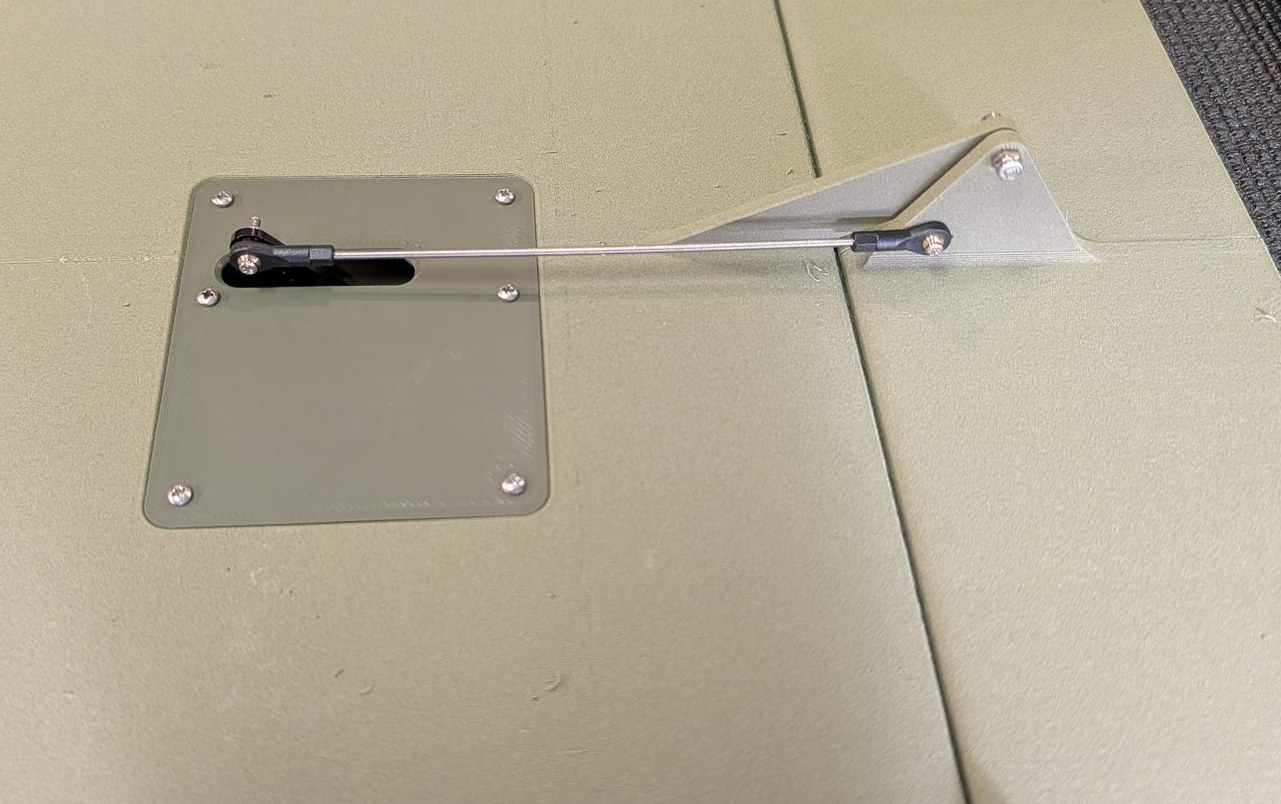
-
Install M3 heat-set threaded inserts into the bolt latch receptacles.
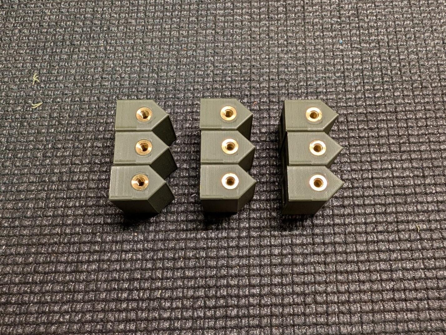
-
Glue two bolt latch receptacles into each wing root, with the threaded inserts facing down. Wing assembly is now complete.
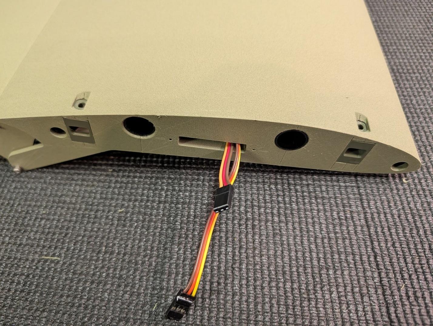
Tail assembly
-
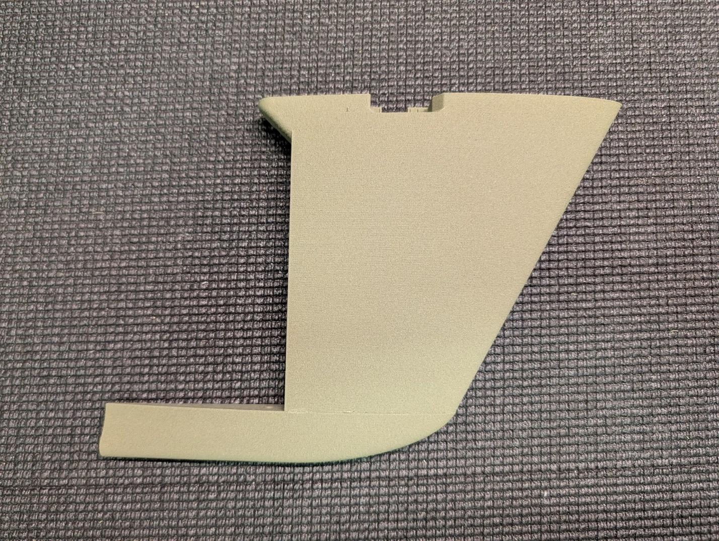
Glue ventral tail sections 1 and 2 together.
-
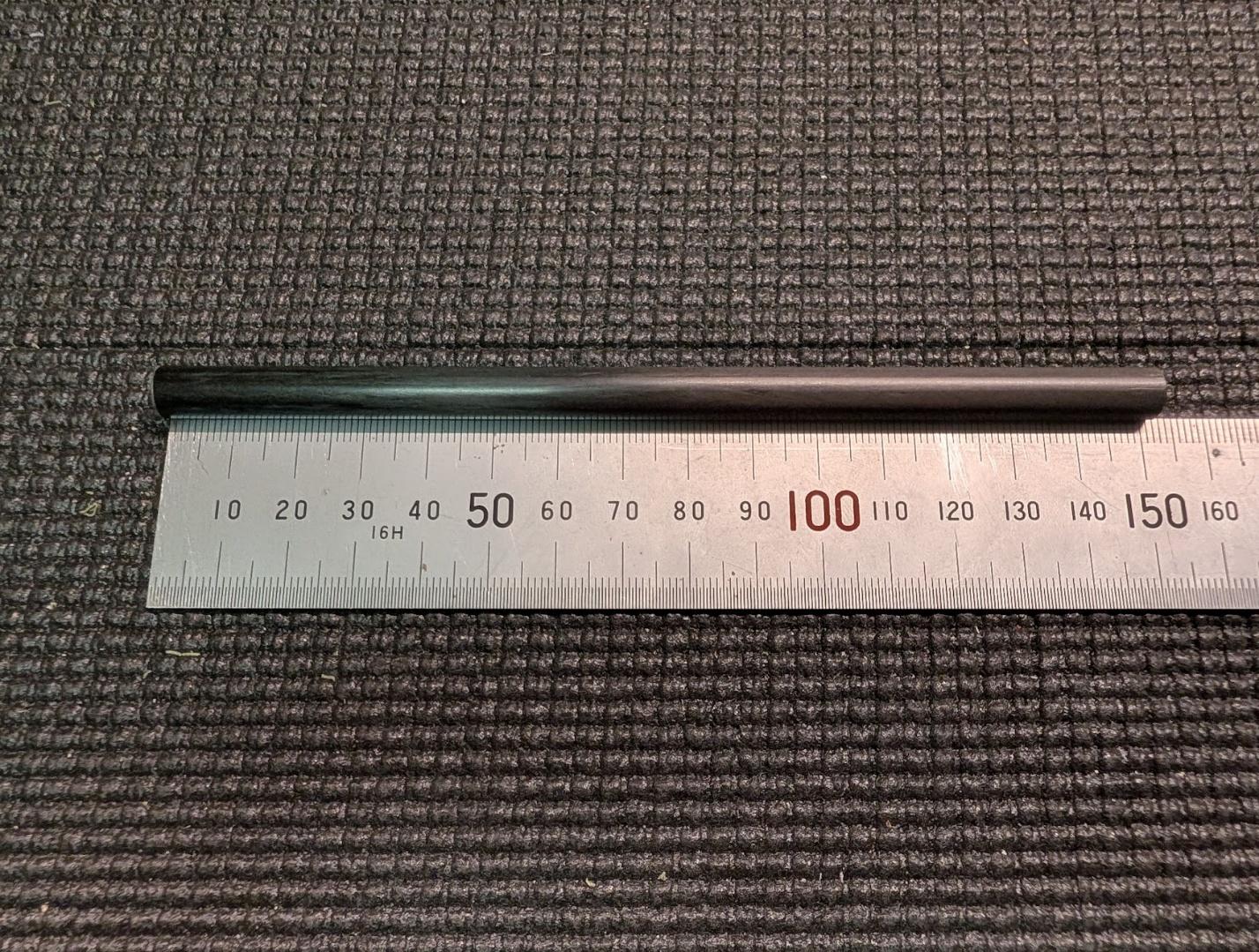
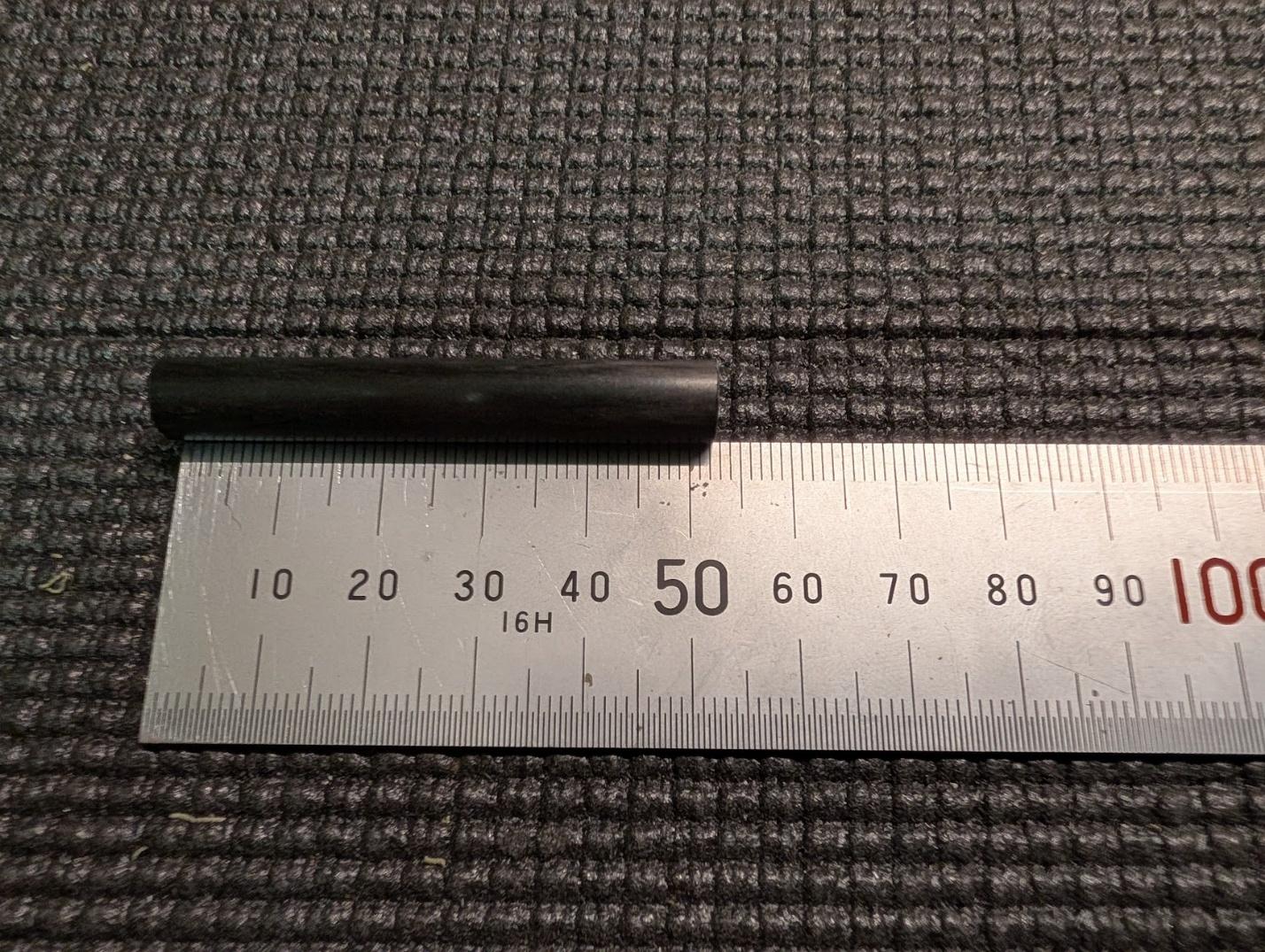
Cut 8mm carbon fiber tube into 152mm and 52mm lengths for the ventral tail spars.
-
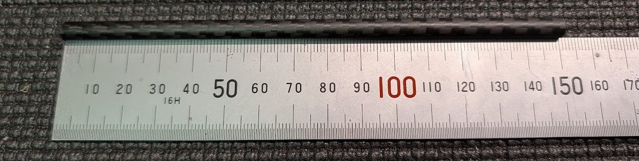
Cut a 4mm carbon fiber tube into a 150mm length for the tail skid.
-
Glue the ventral tail spars and tail skid into the joined ventral tail assembly as shown.
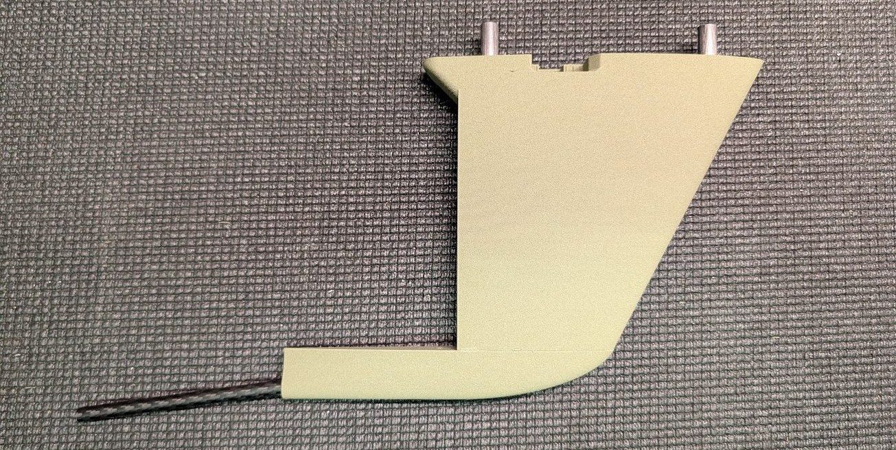
-
Cut a 2mm carbon rod into a 157mm length for the rudder hinge.
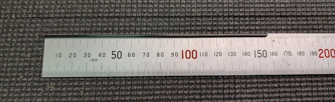
-
Join the two sections of the rudder, using the rod for alignment if desired.
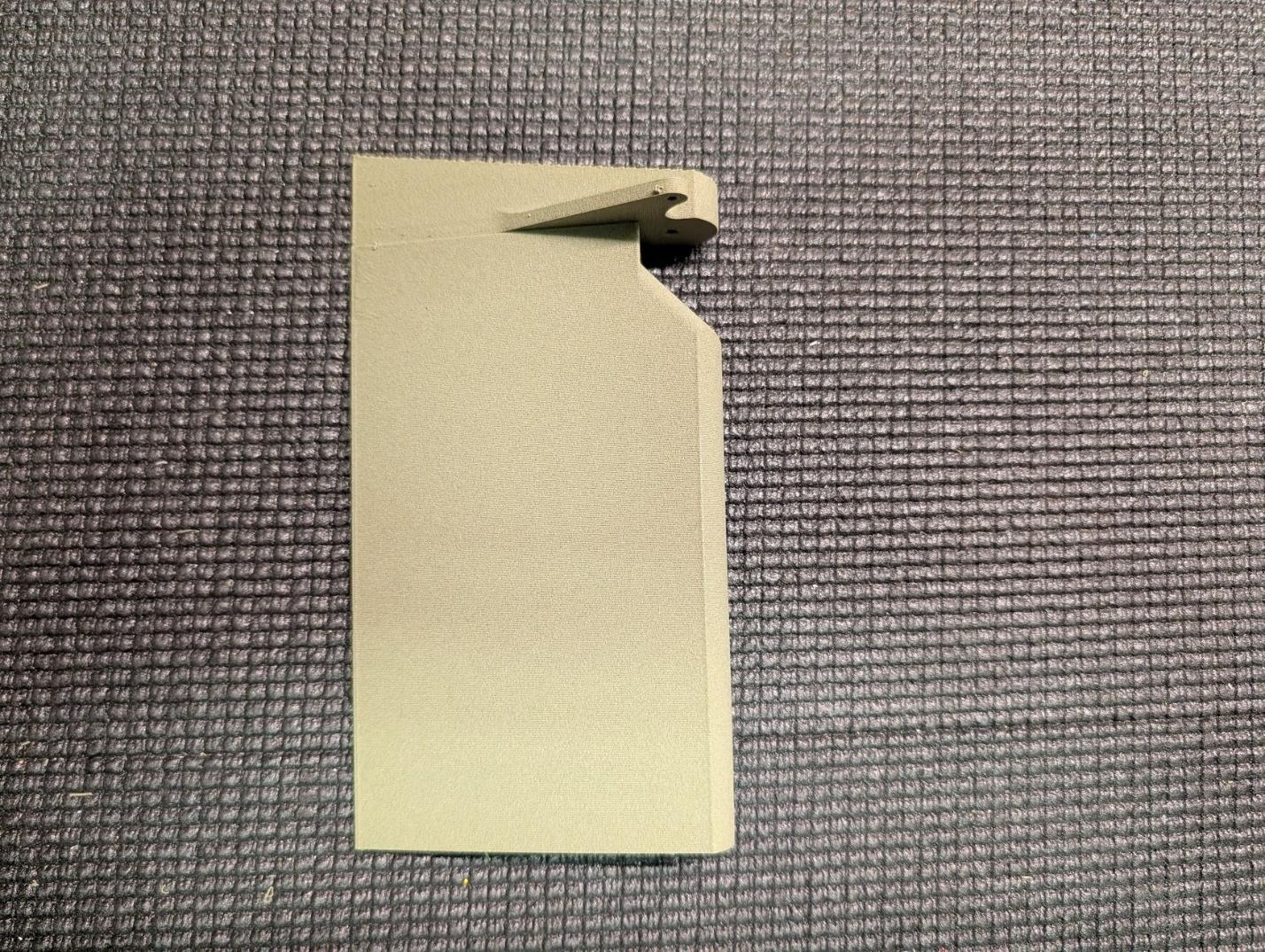
-
Install the rudder with the carbon fiber hinge rod, securing the rod with a drop of glue at the root.
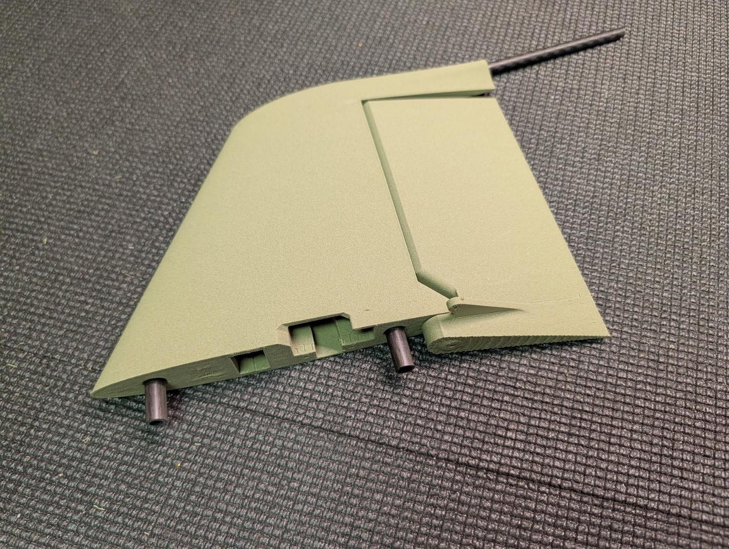
-
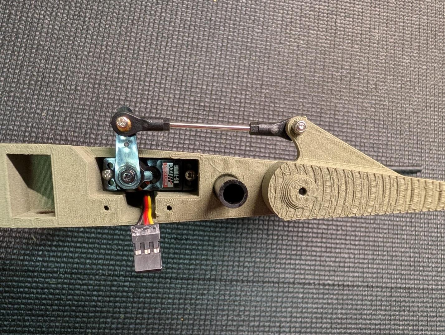
Center the rudder servo and mount it with #2 x 3/8" tapping screws. Create a pushrod using M2 threaded rod and ball links. Coil the lead under the servo, leaving enough to comfortably plug into the fuselage.
-
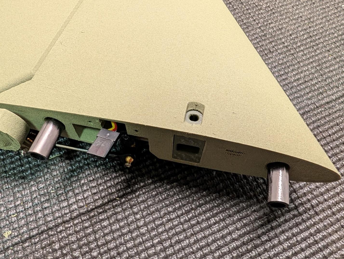
Glue a bolt latch receptacle into the ventral tail as shown.
-
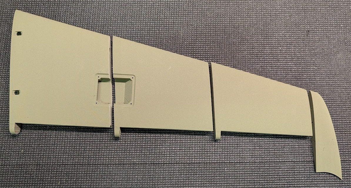
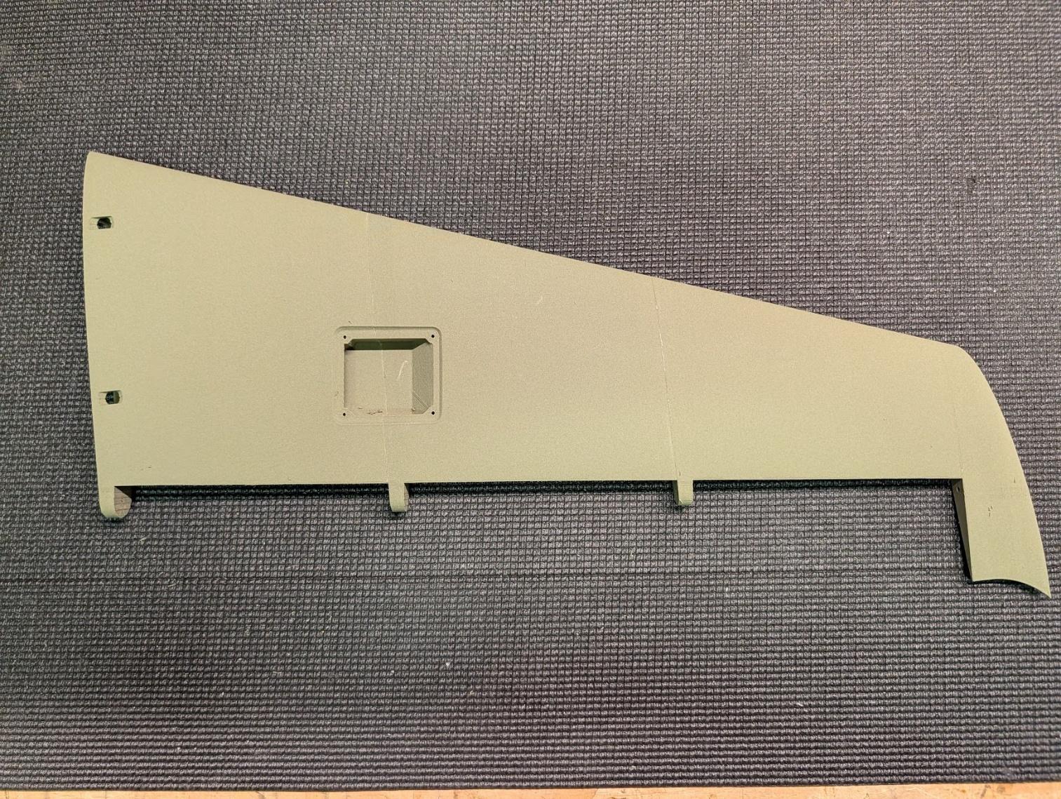
Using filament guide pins as necessary, glue together the four sections of each tail surface.
-
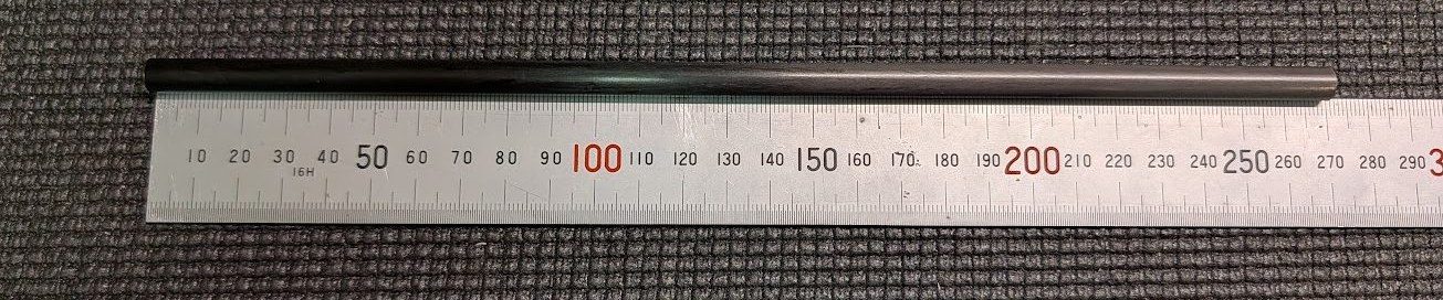
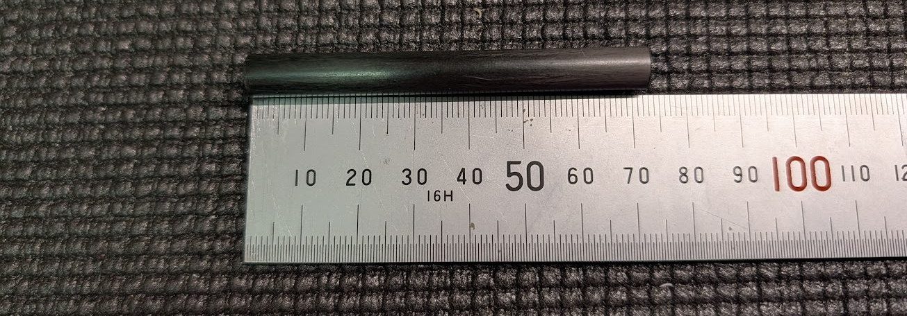
Cut two 270mm and two 74mm lengths of the 8mm carbon fiber tube to serve as the forward and aft tail spar tubes, respectively.
-
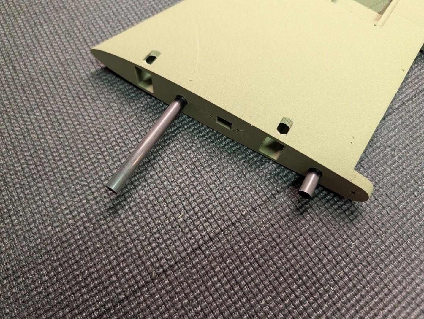
Glue the forward and aft spars into the tail surfaces.
-
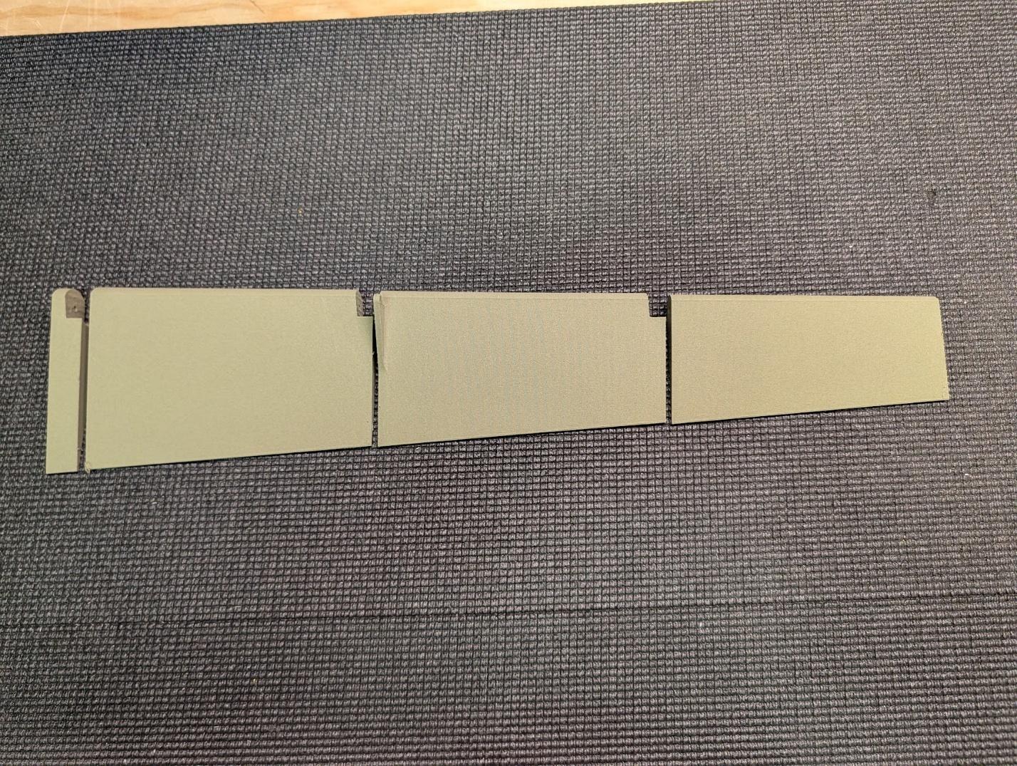
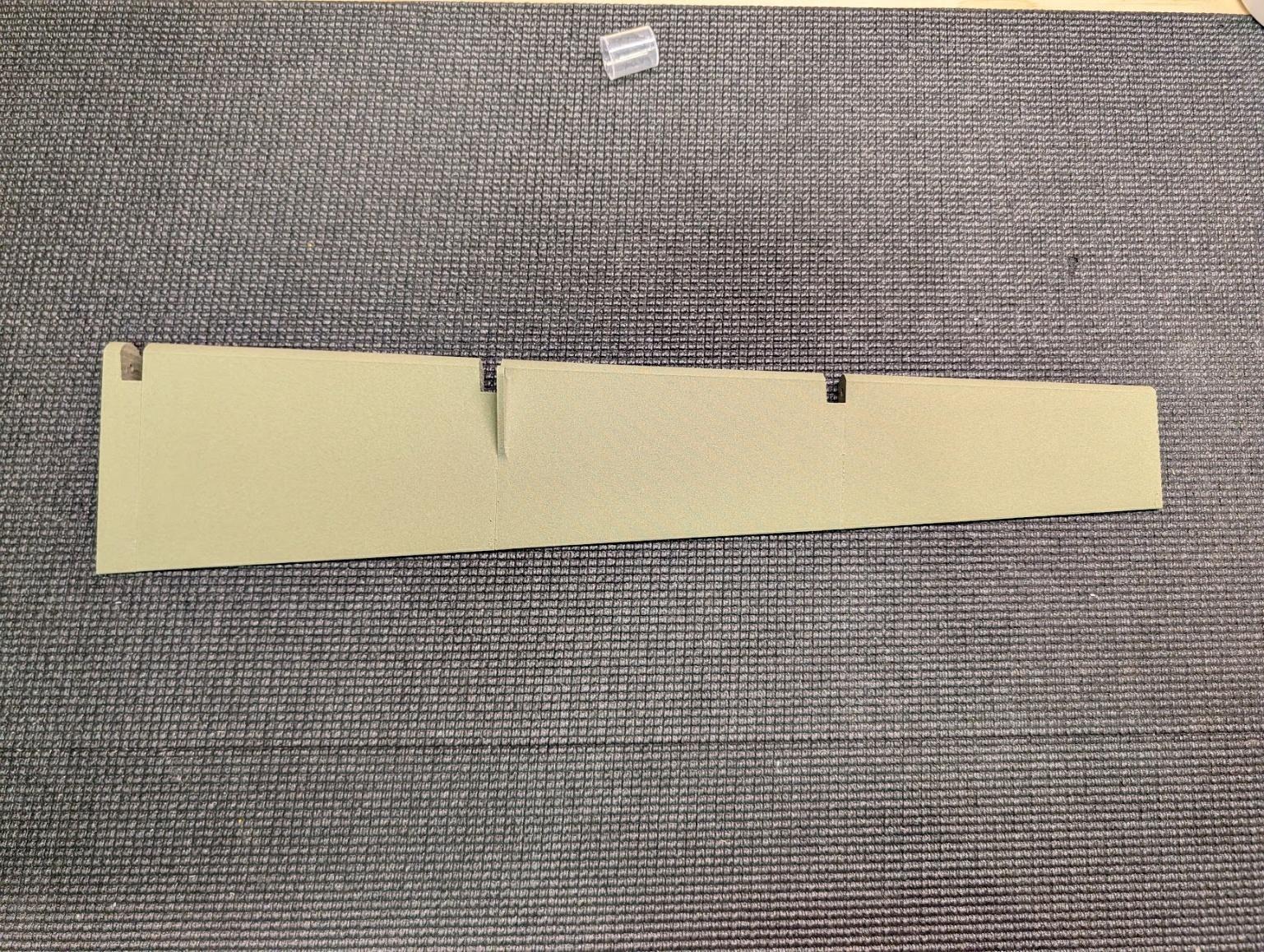
Join the four sections of each elevator surface.
-
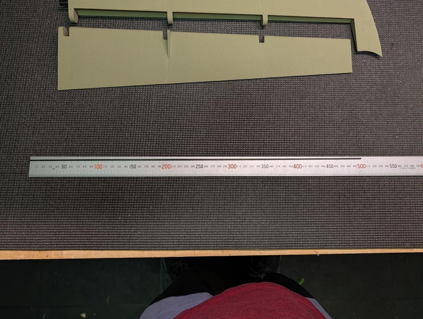
Cut two 500mm lengths of 2mm solid carbon fiber rod to serve as the elevator hinges.
-
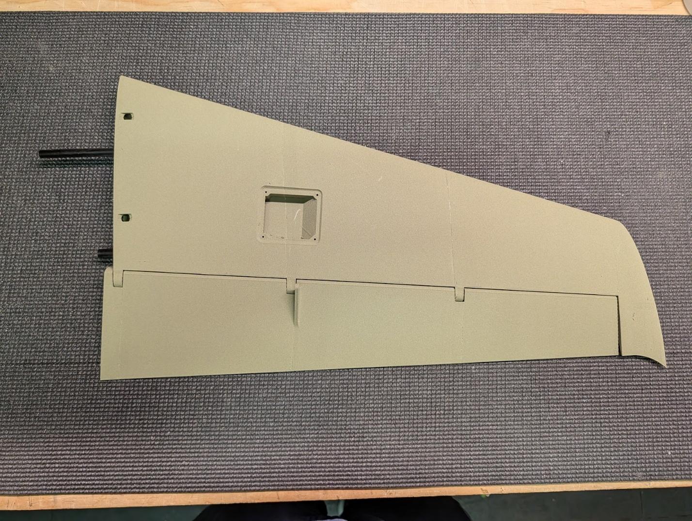
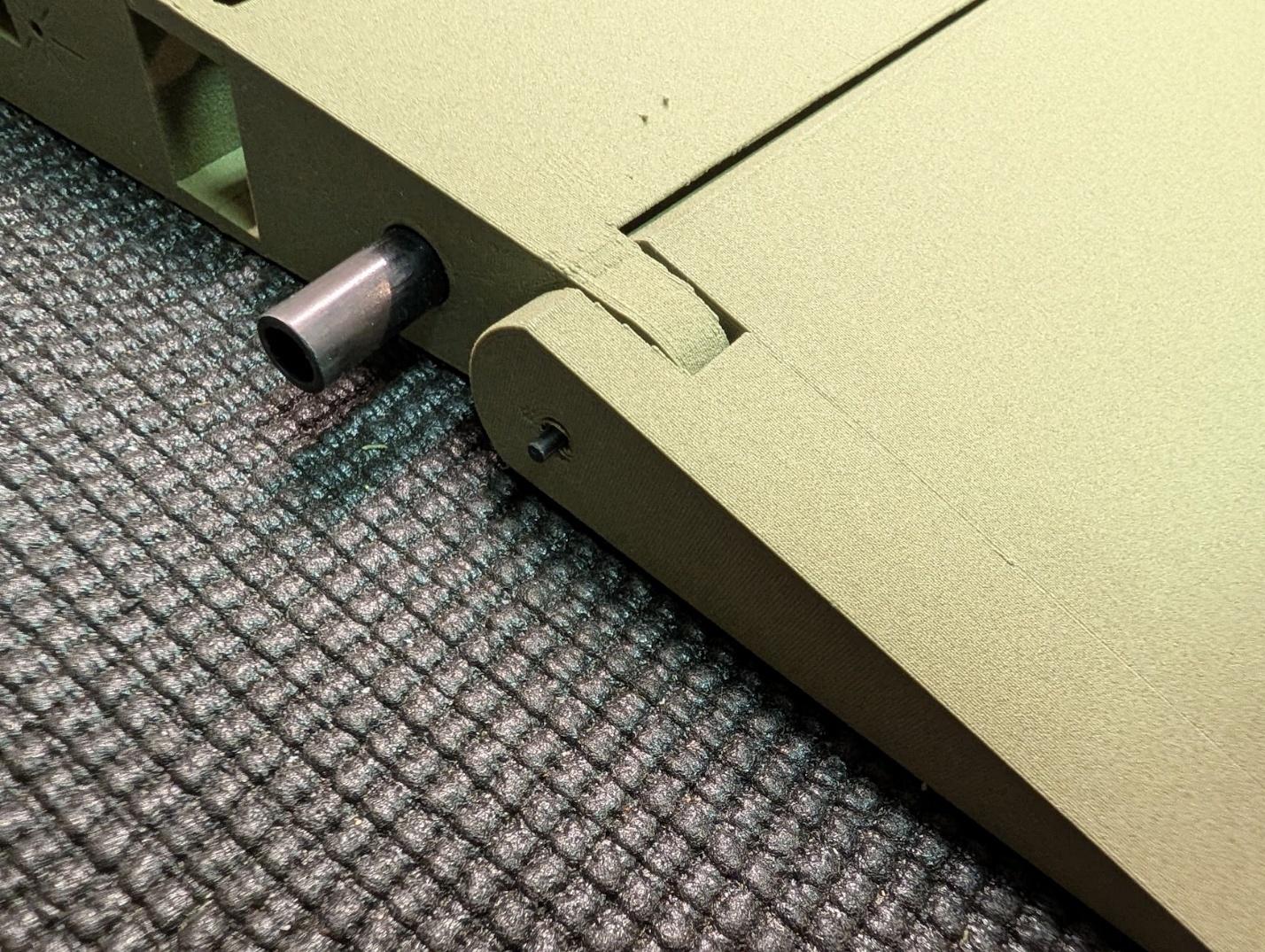
Use the carbon fiber hinge rods to install the elevator surfaces. The hinge rod will protrude from the root a small amount – this is expected.
-
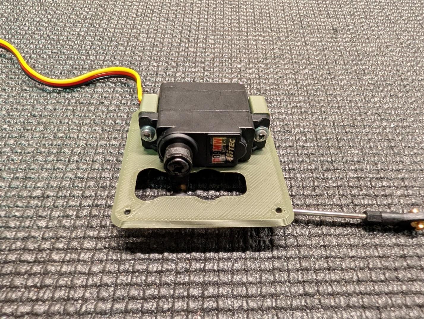
Prepare the elevator servos, mounts, and covers in the same fashion as the aileron servos.
-
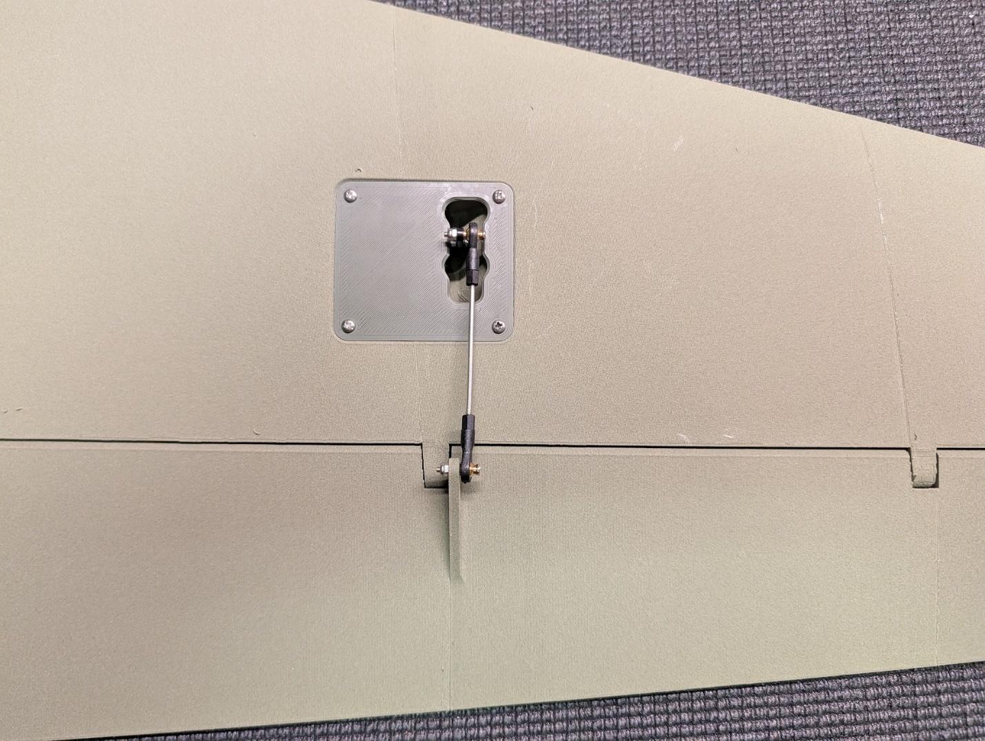
Install the servos and pushrods with #2 x 3/8" self-tapping screws, M2 threaded rods, and ball links.
-
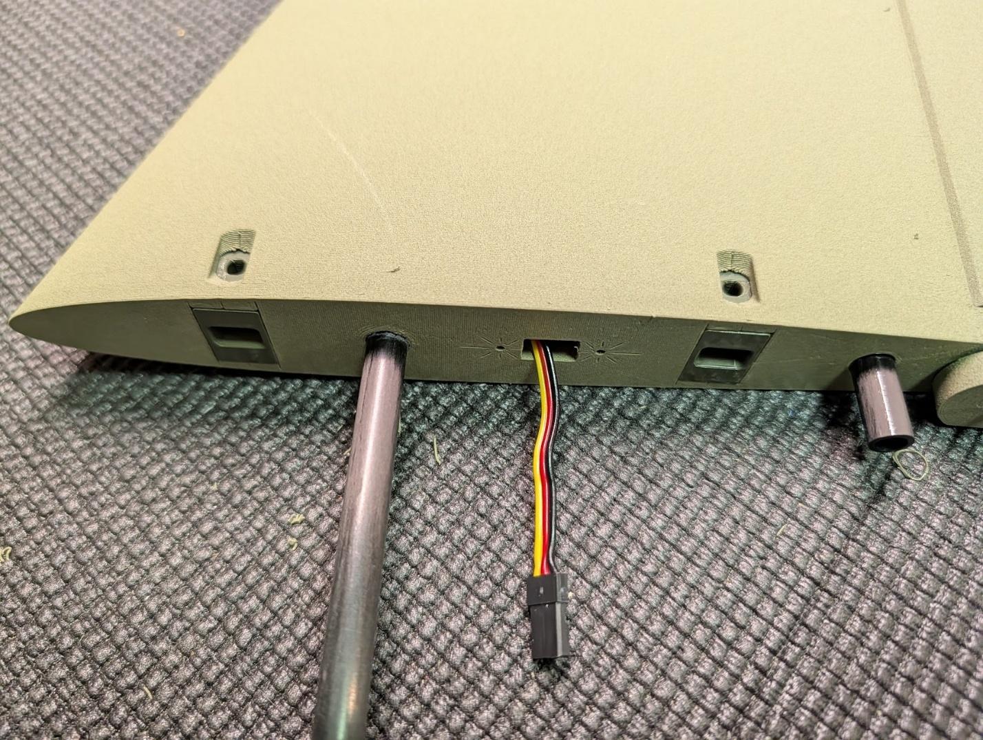
Install two bolt latch receptacles in the root of each tail surface to complete the tail assembly.
Fuselage assembly
-
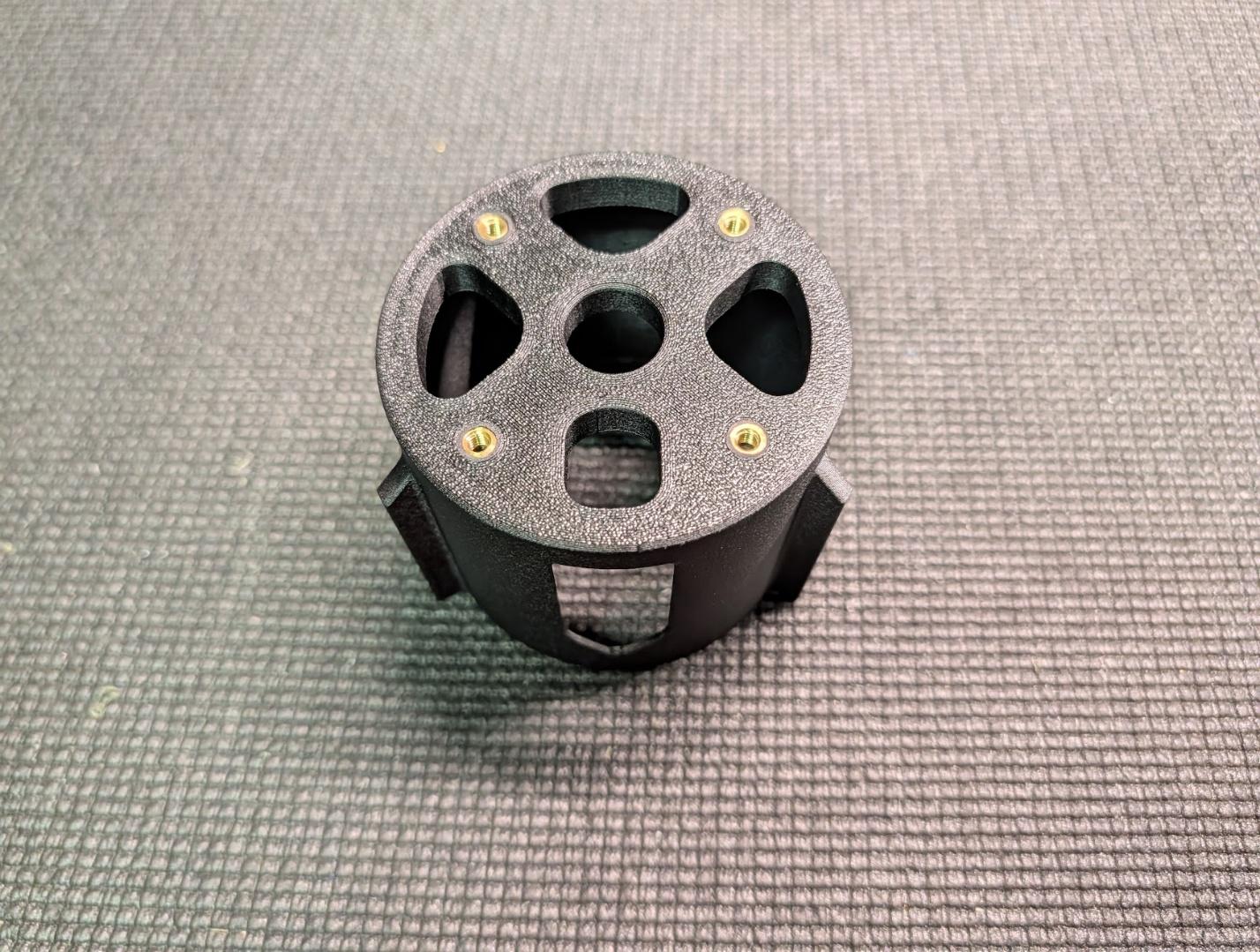
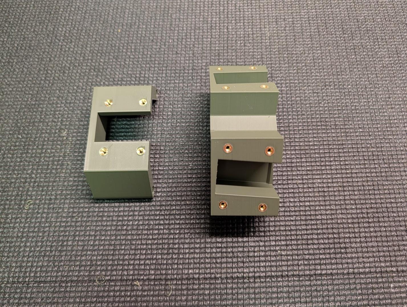
Install M4 heat-set threaded inserts into the motor mount.
-
Install M3 heat-set threaded inserts into the main and nose landing gear mounts.
-
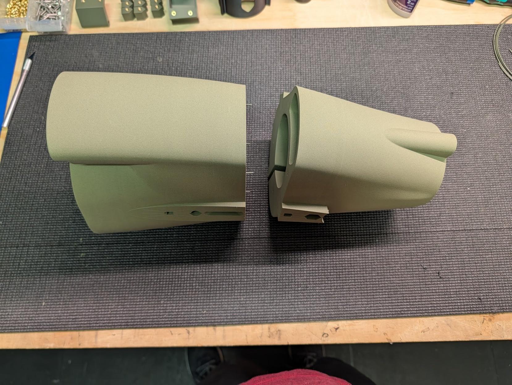
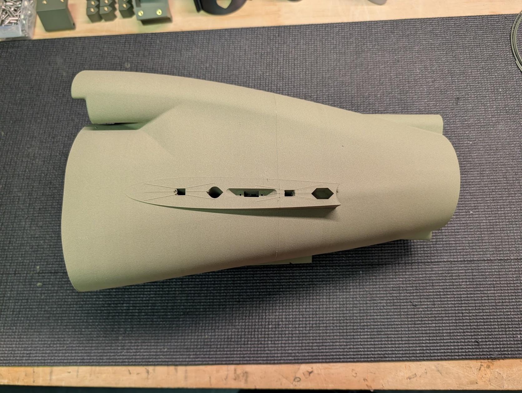
Using filament guide pins, join fuselage sections 8 and 9.
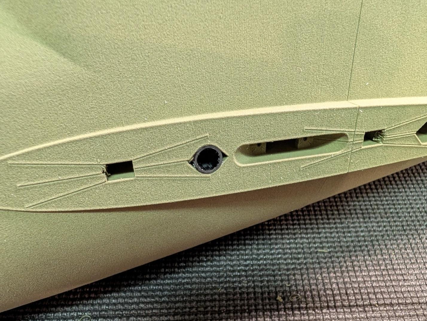
-
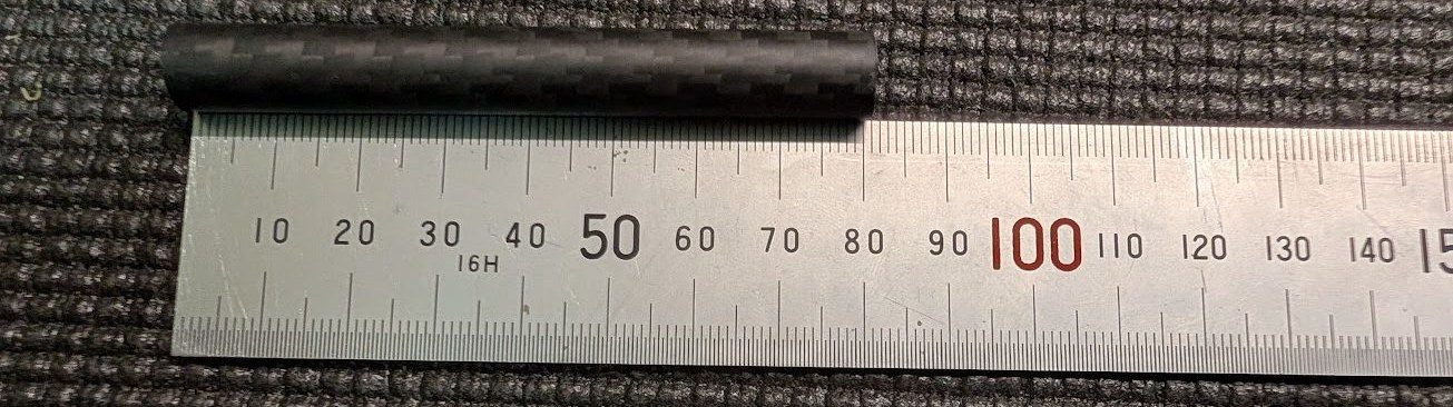
Cut two 80mm lengths of 10mm carbon fiber tube. These will receive the 8mm forward tail spars – test to ensure that they slide together easily.
-
Glue the 80mm tail joiner sleeves into the aft fuselage.
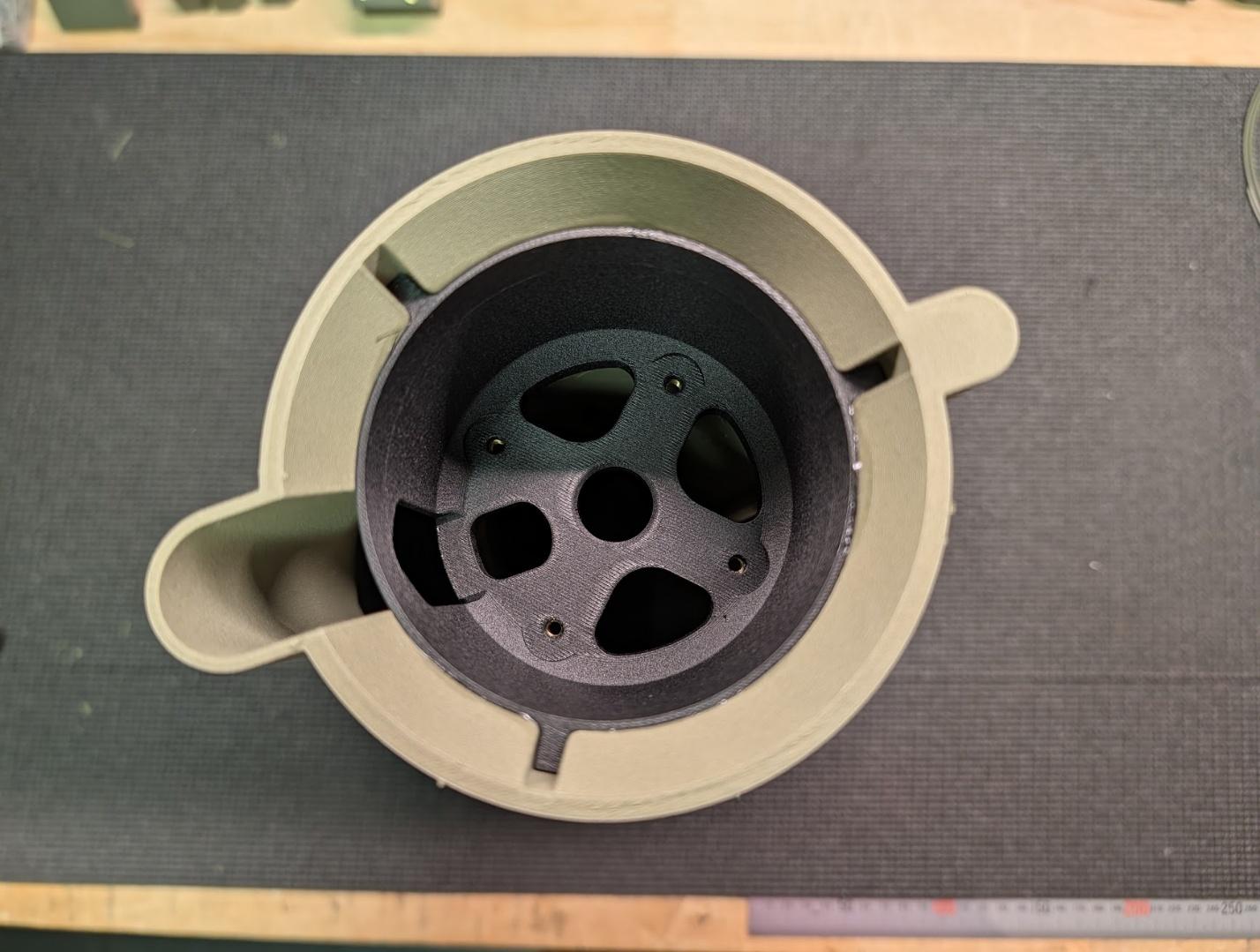
-
Now is also a good time to glue the motor mount into the aft fuselage. Use a strong, slow-curing glue such as epoxy.
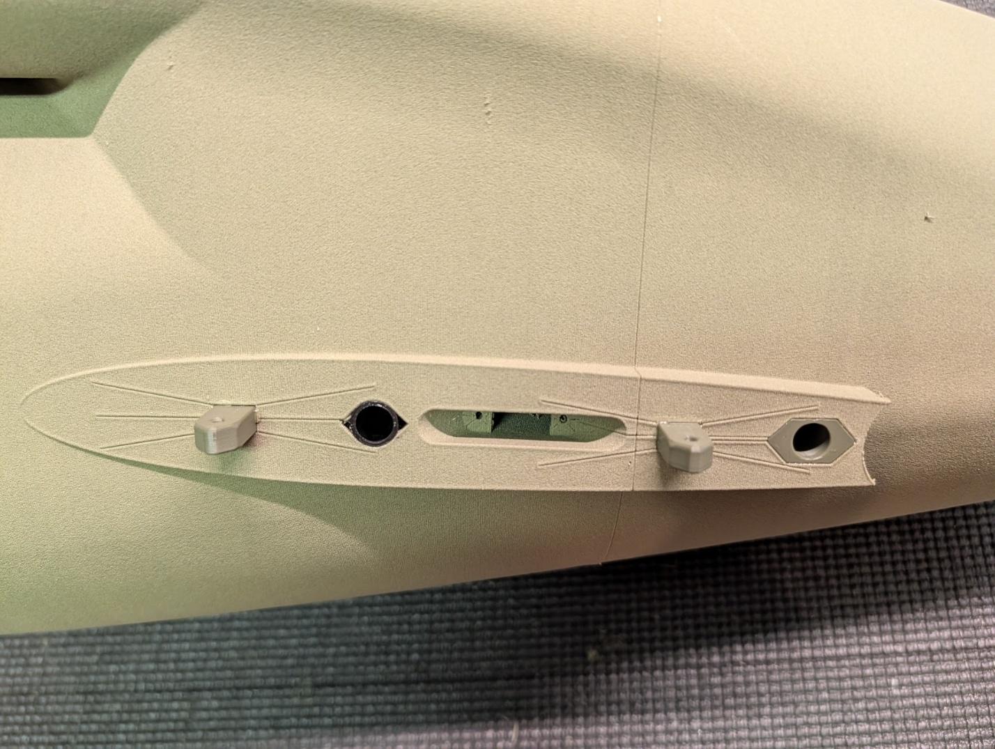
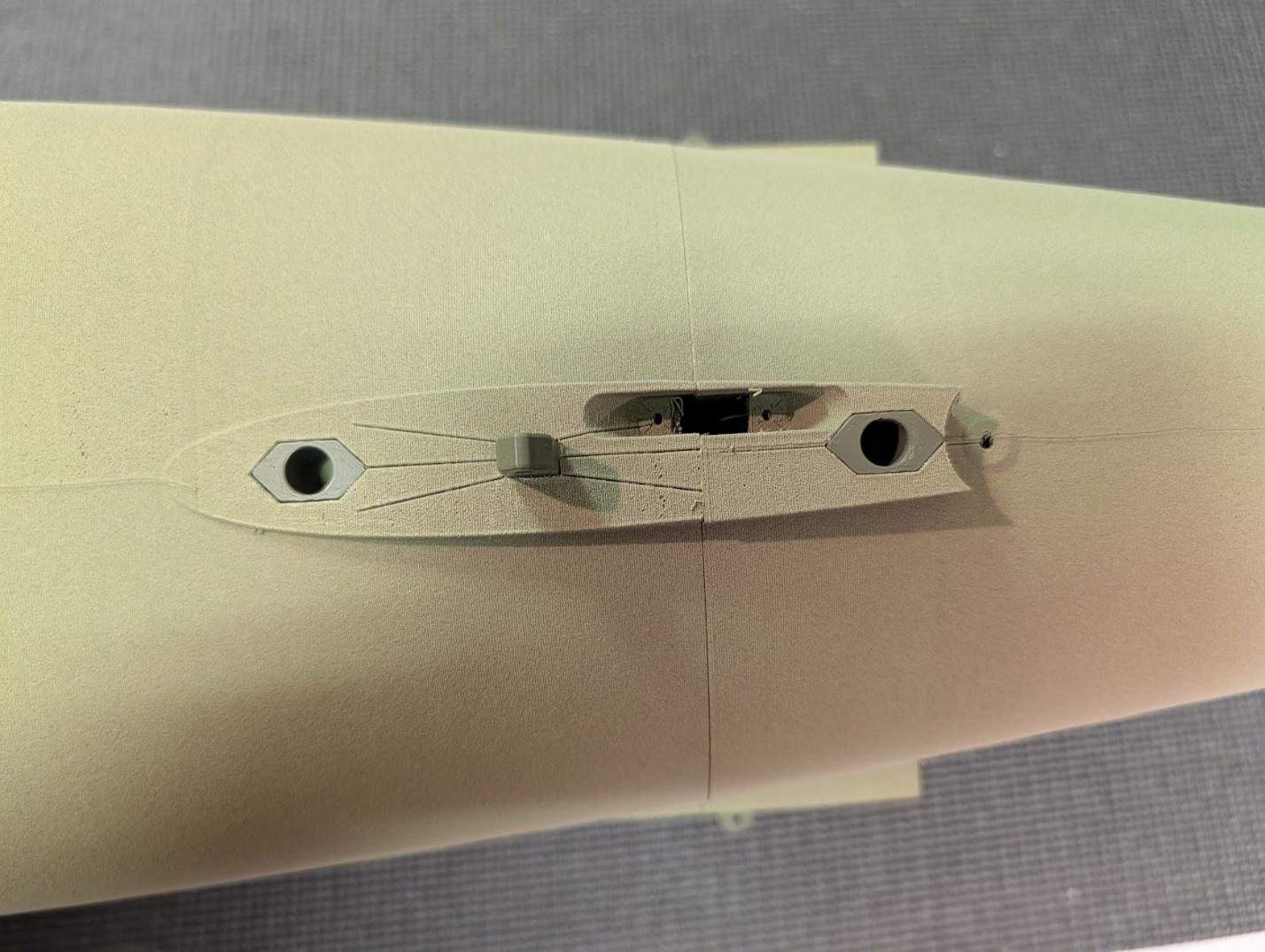
-
Glue the bolt latch tabs and 8mm tube receptacles into their slots in the tail and ventral mating areas of the aft fuselage.
-
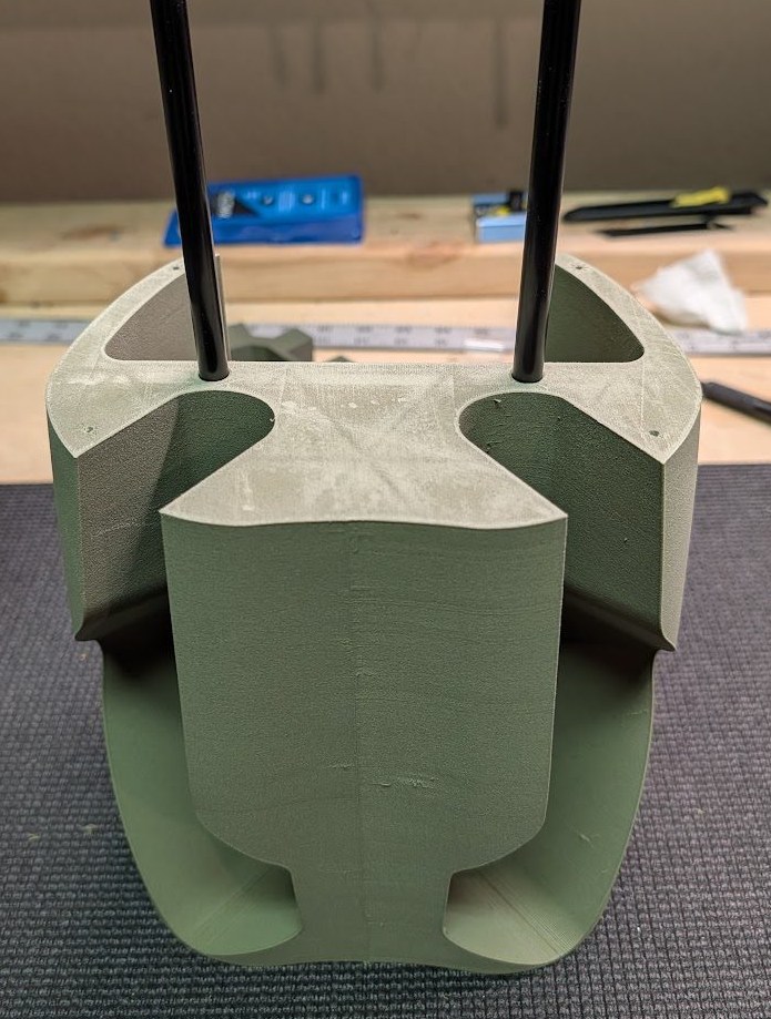
Glue two 8mm x 1000mm carbon fiber tubes into their receptacles in fuselage section 7.
-
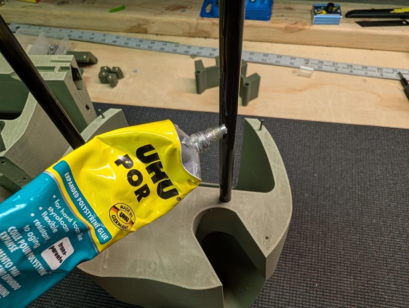
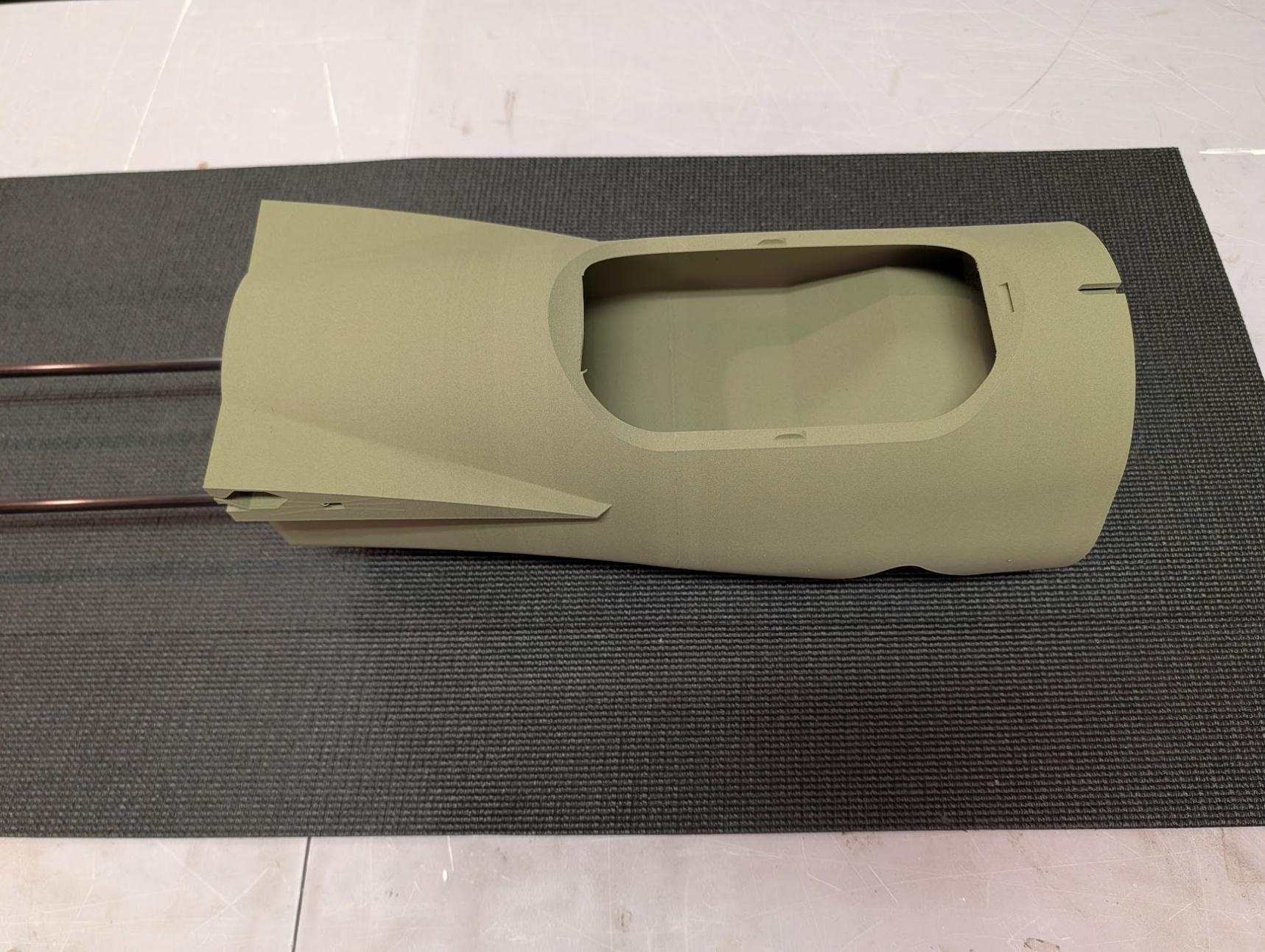
Apply a slow-curing adhesive like UHU or epoxy to the area of the tubes that will interface with fuselage section 6. Then, use filament guide pins and CA to join the mating faces of sections 6 and 7.
-
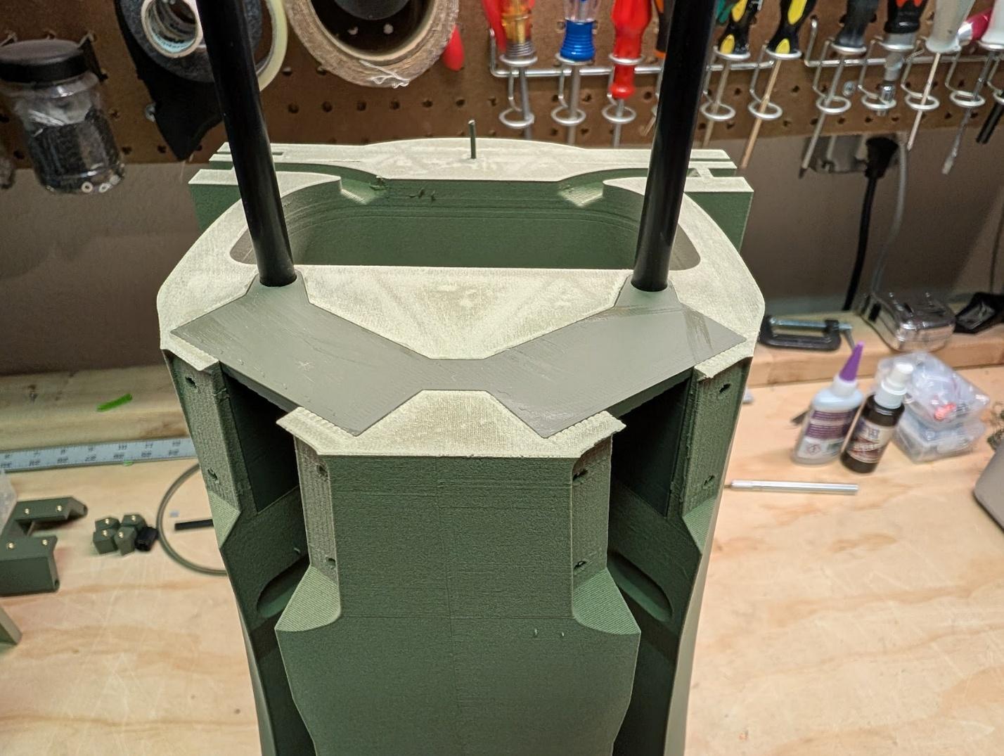
Install the main gear mount into its pocket in fuselage section 6 and secure with CA.
-
Using the same UHU/epoxy + CA process as previously, join section 5 to section 6.
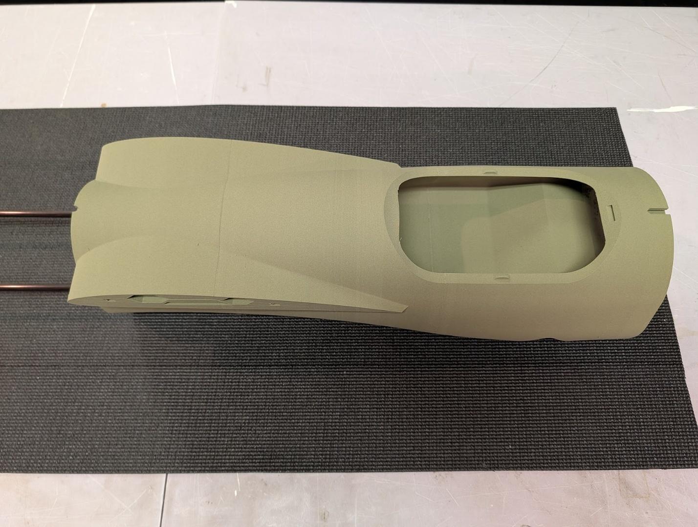
-
Slide a pen spring and the forward hatch latch into the slot in fuselage section 5. Then glue on section 4, using care not to get glue on the moving latch parts.
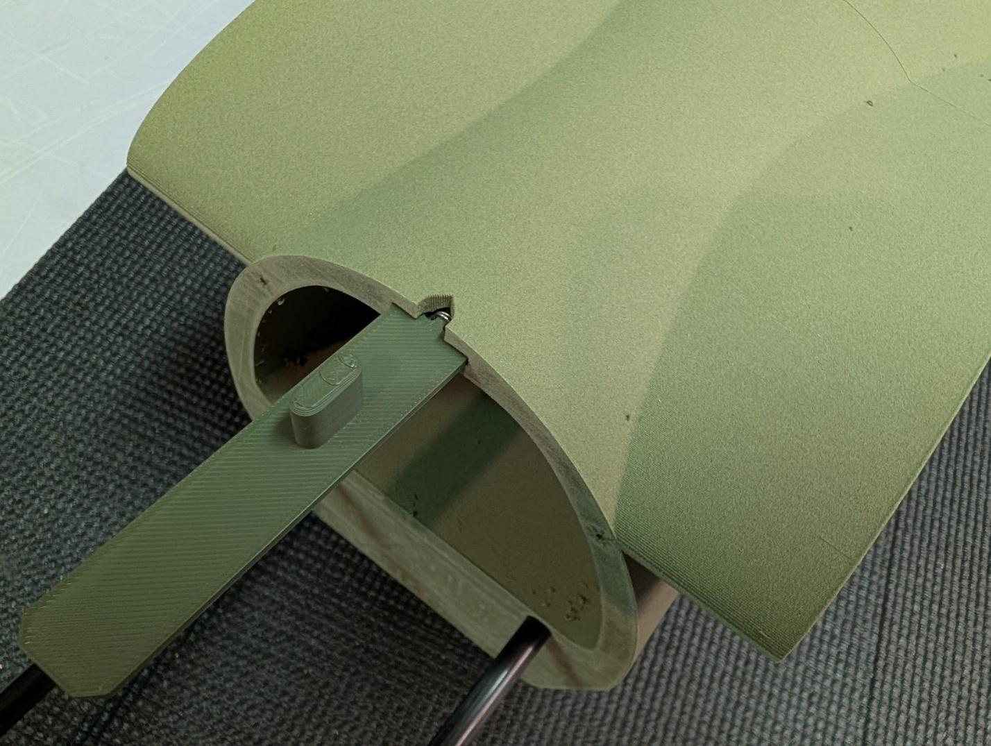
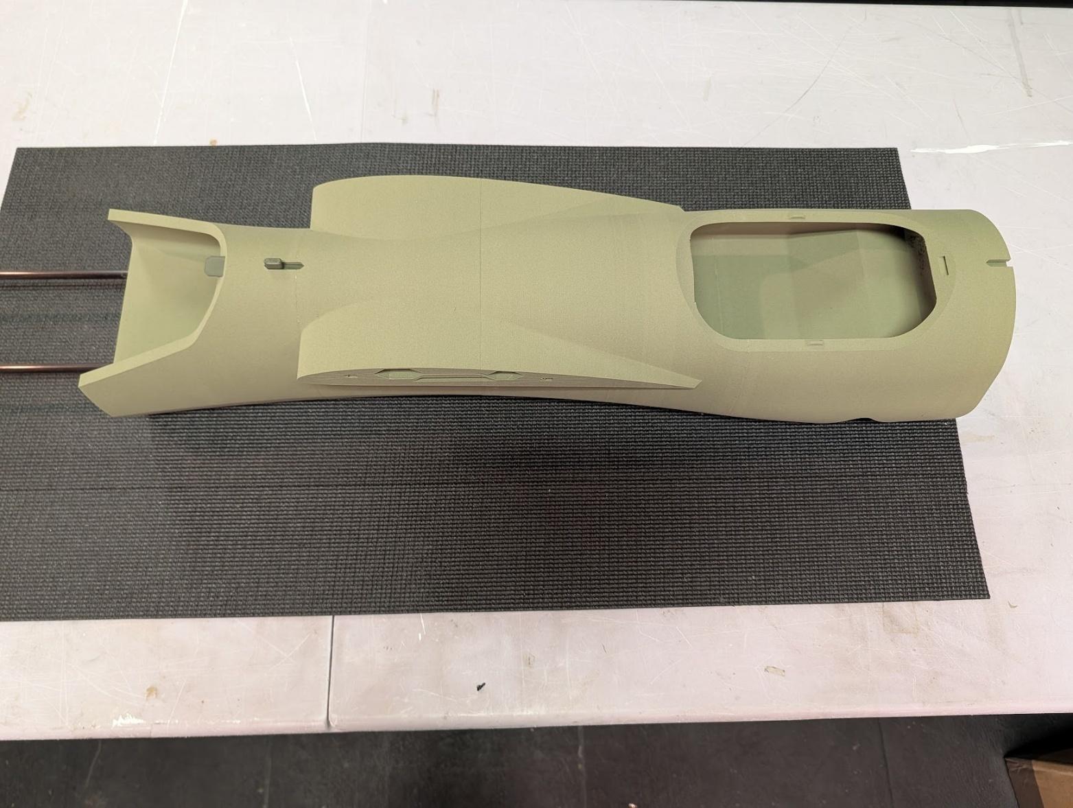
-
Continue fuselage assembly by attaching section 3.
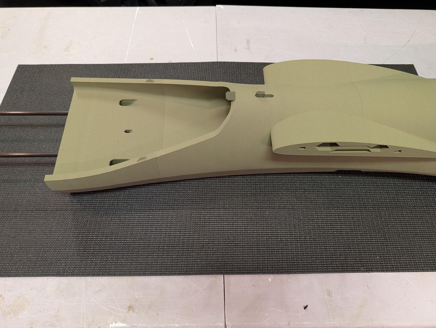
-
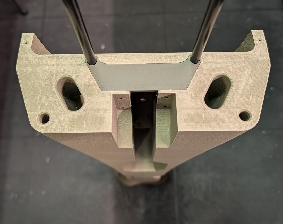
Similarly to the main gear mount installed previously, slide the nose gear mount into its pocket in fuselage section 2 and secure with CA.
-
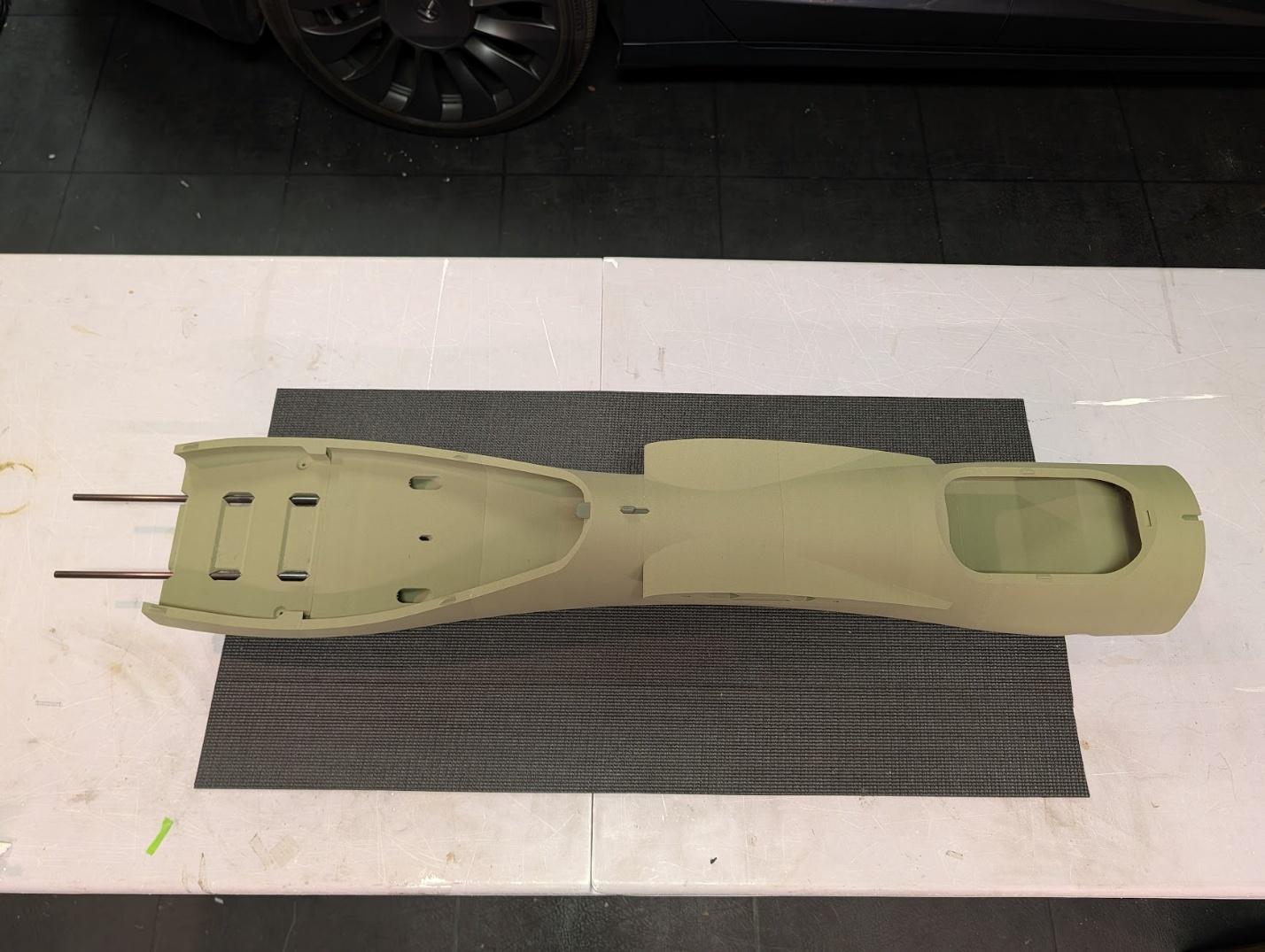
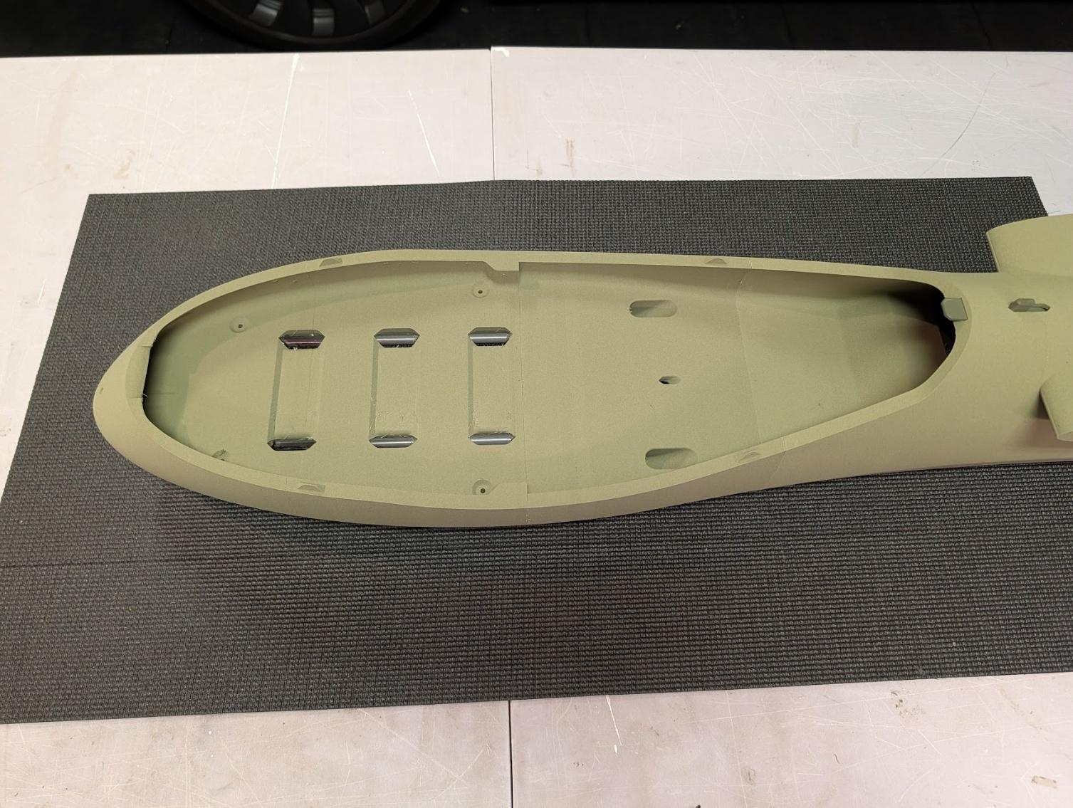
Complete the forward fuselage assembly by adding sections 1 and 2.
-
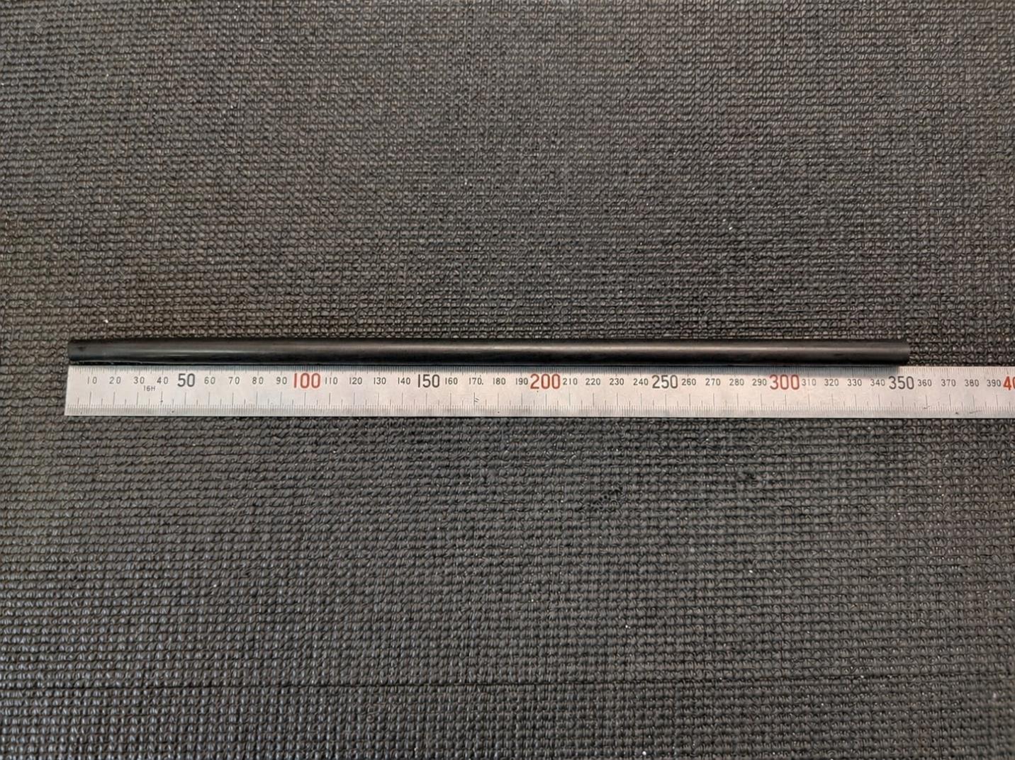
Cut a 350mm length of 8mm carbon fiber tube to serve as the lower joiner between the forward and aft fuselage sections.
-
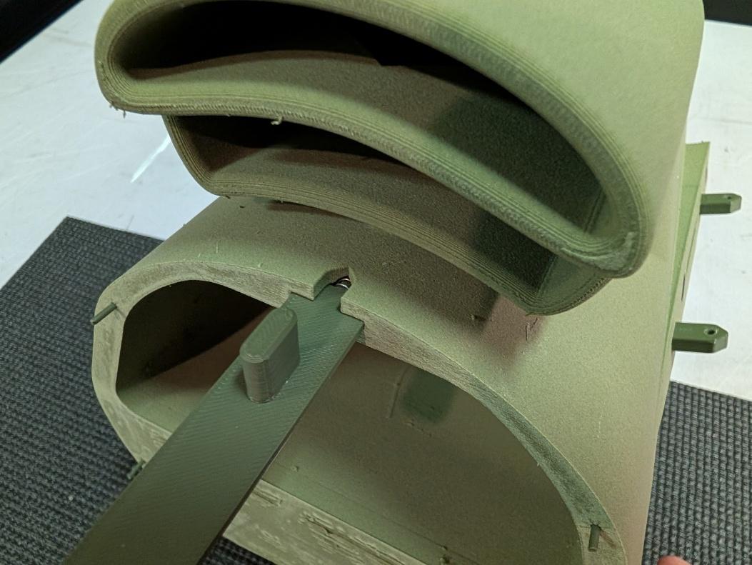
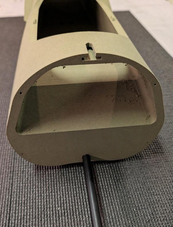
Slide a pen spring and the rear hatch latch into its slot on fuselage 8. Slide the lower joiner tube into the hole in fuselage 7.
-
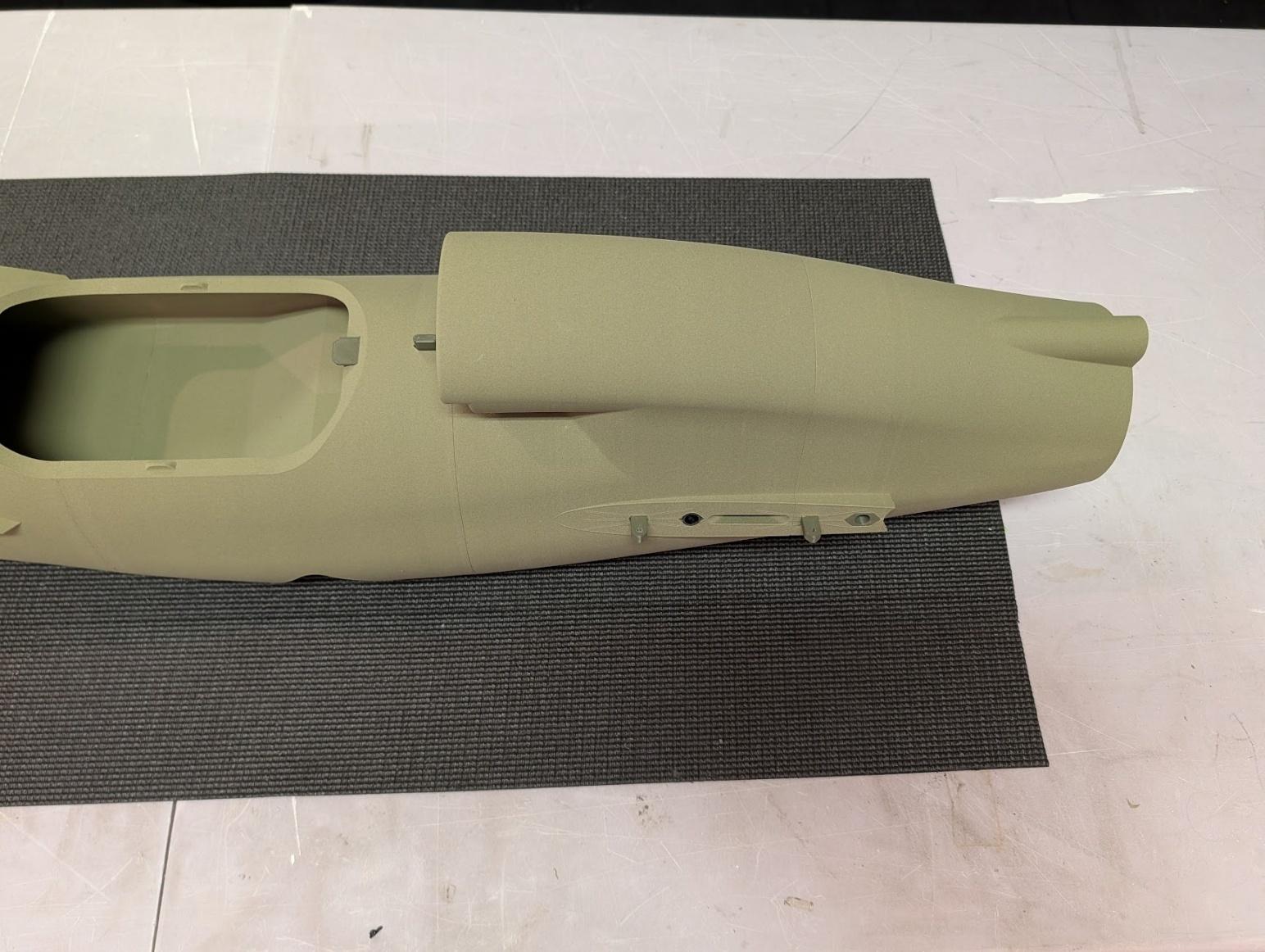
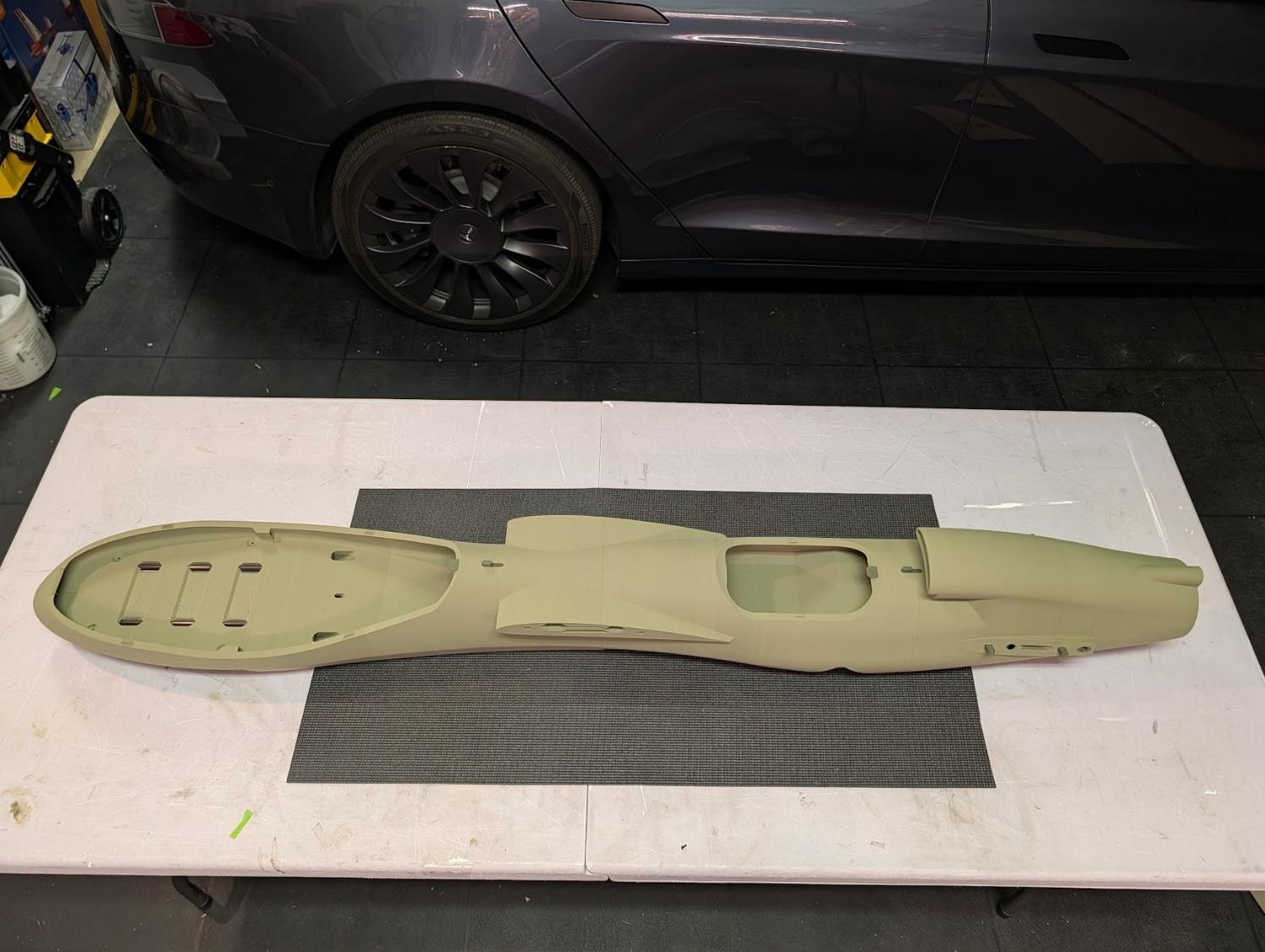
Join the forward and aft fuselage assemblies together to complete the main fuselage assembly. The lower joiner tube will extend all the way into Fuselage 6 and should be secured with slow-curing glue.
-
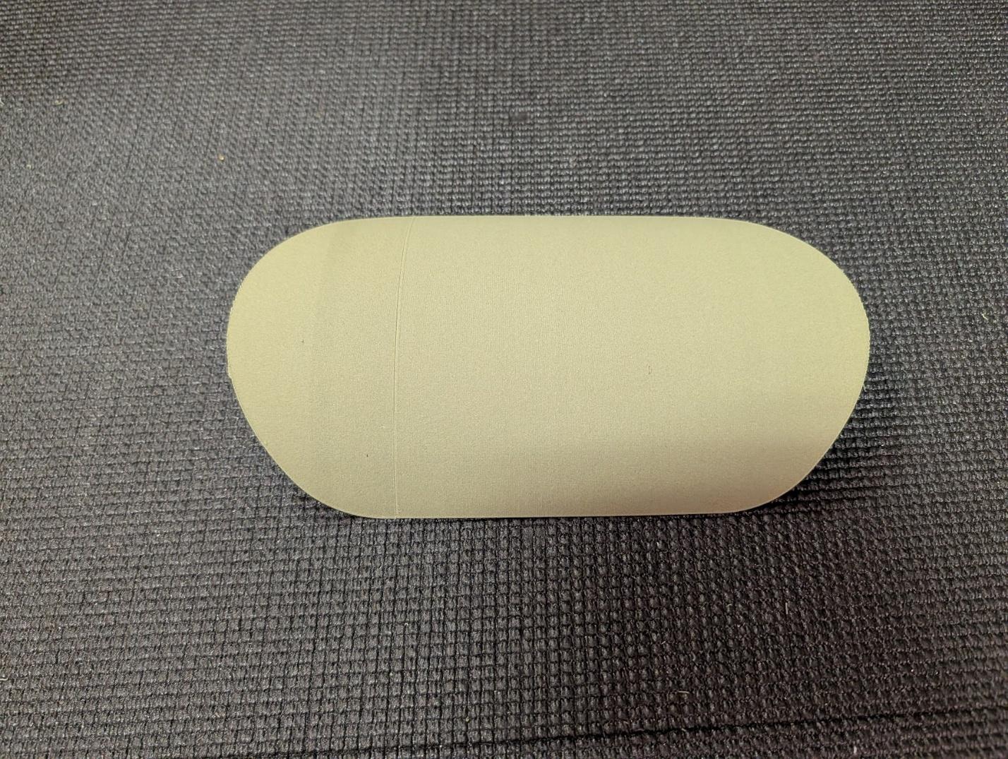
Join the two sections of the rear hatch.
-
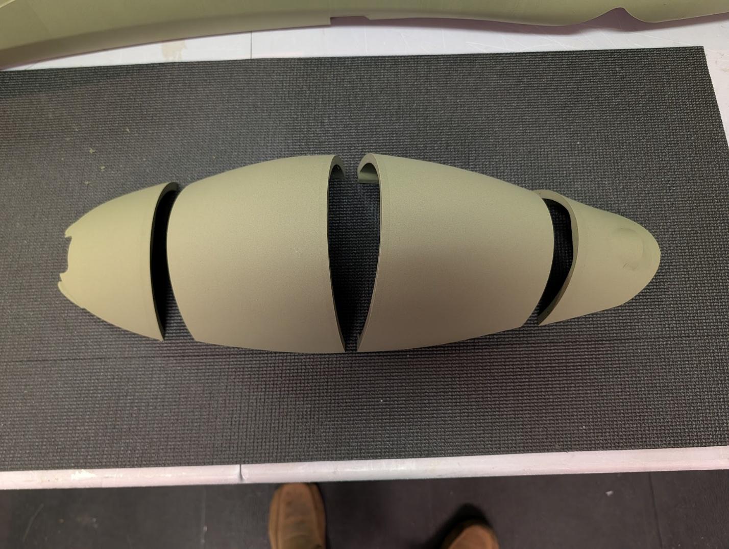
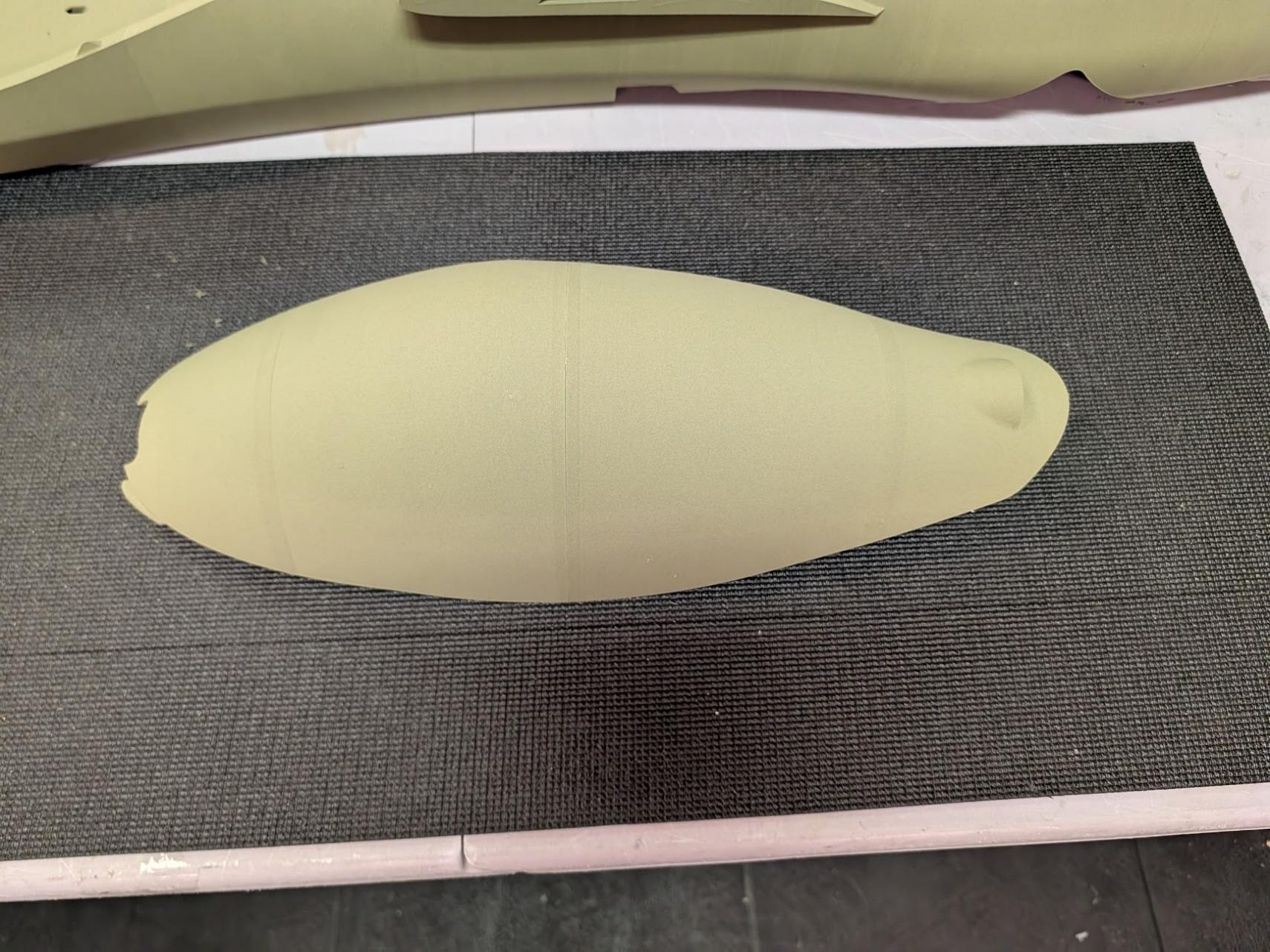
Join the four sections of the canopy.
-
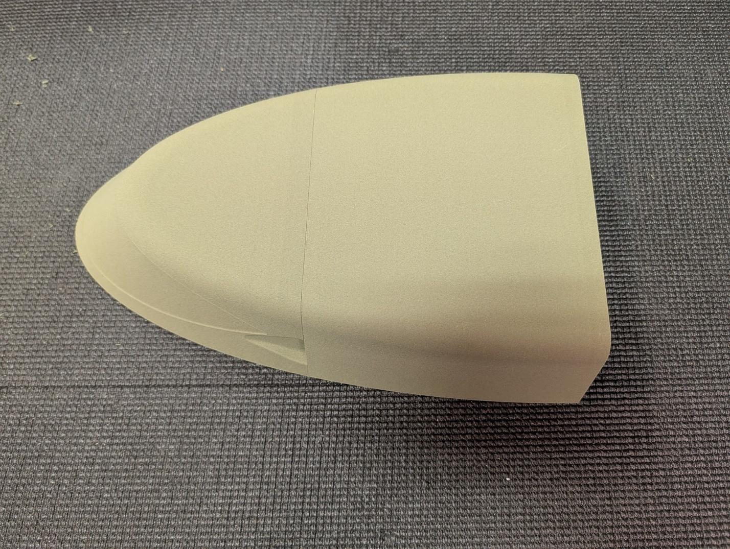
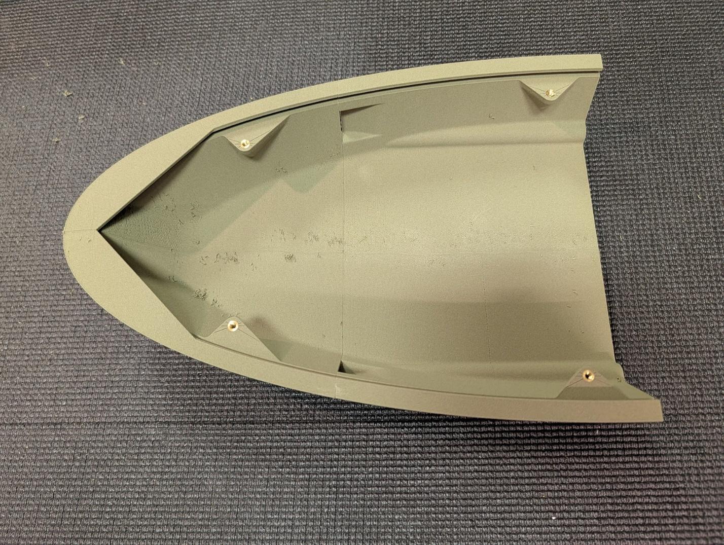
Join the two sections of the nose and install four M3 heat-set threaded inserts.
-
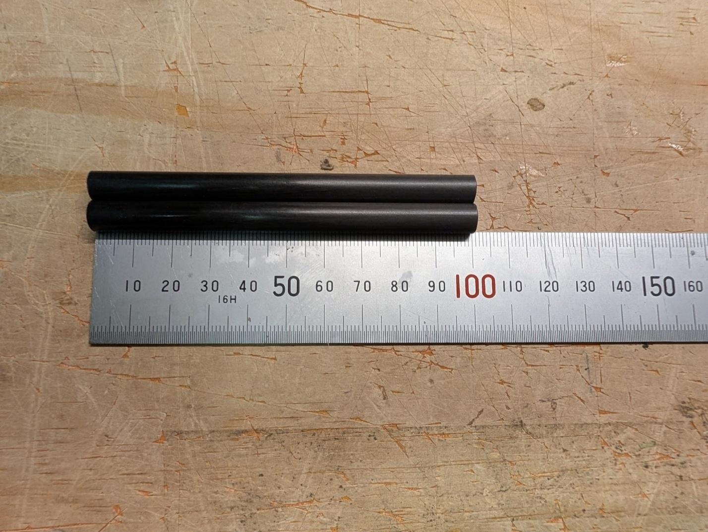
Cut two 100mm lengths of 8mm carbon fiber tube to serve as the nose joiners.
-
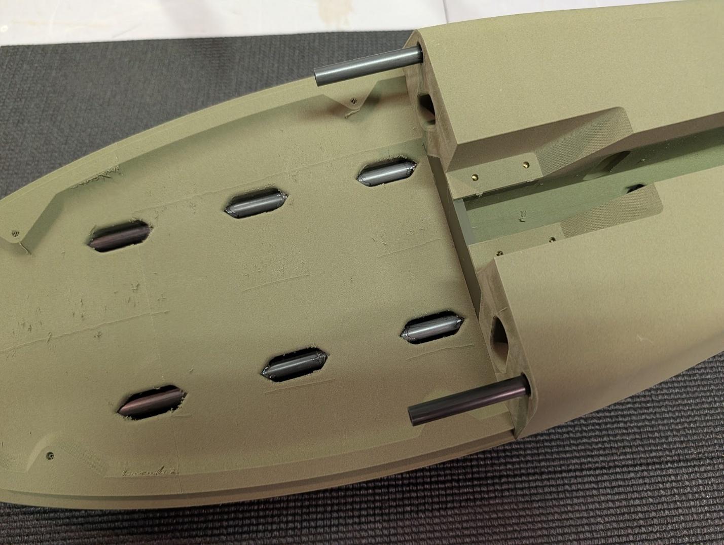
Glue the nose joiner tubes into their pockets in the forward fuselage.
-
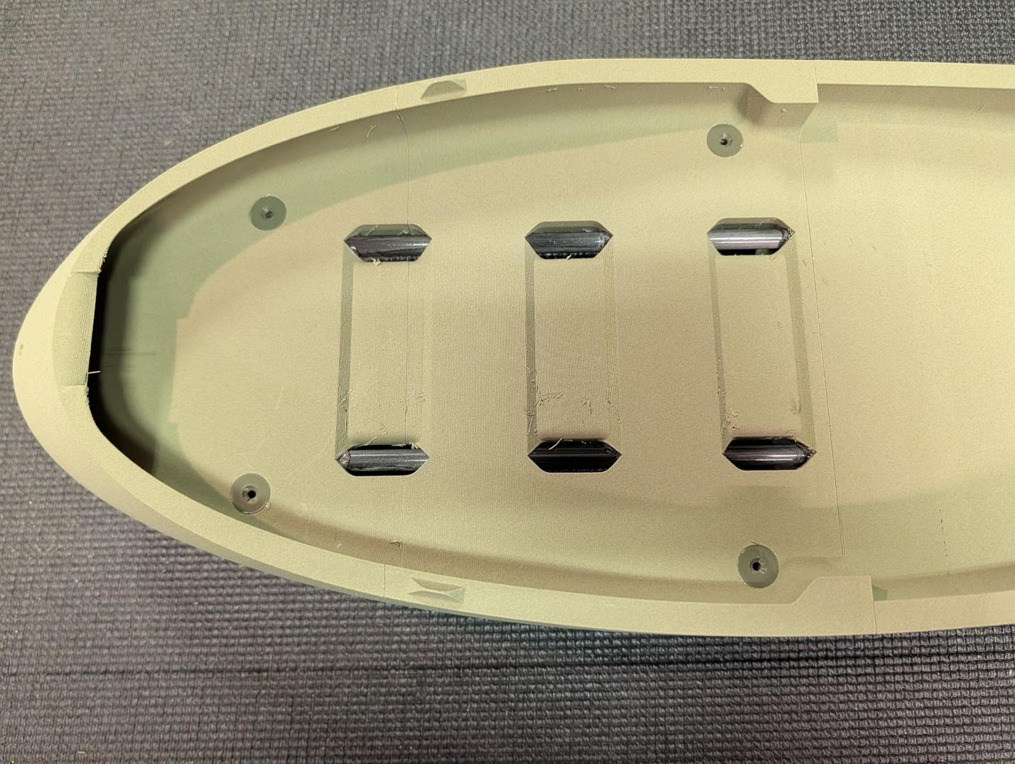
Glue the nose mounting screw doublers into their pockets in the battery tray area.
-
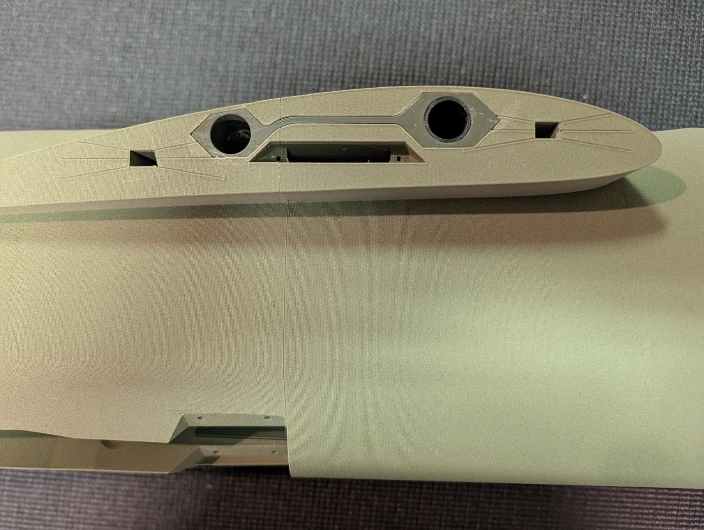
Glue the wing spar guides into their pockets in the fuselage. Insert and glue a ~158mm length of 16mm carbon fiber tube (this is the part left over from cutting the two 420mm aft joiner sleeves) into the forward hole in the guides.
-
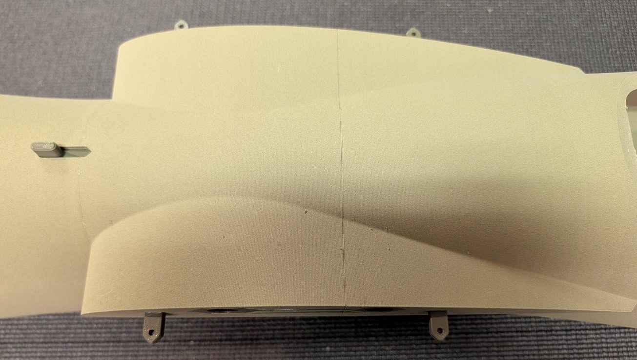
Insert and glue the four bolt latch tabs into the wing root area to complete the fuselage assembly.
Landing gear assembly
-
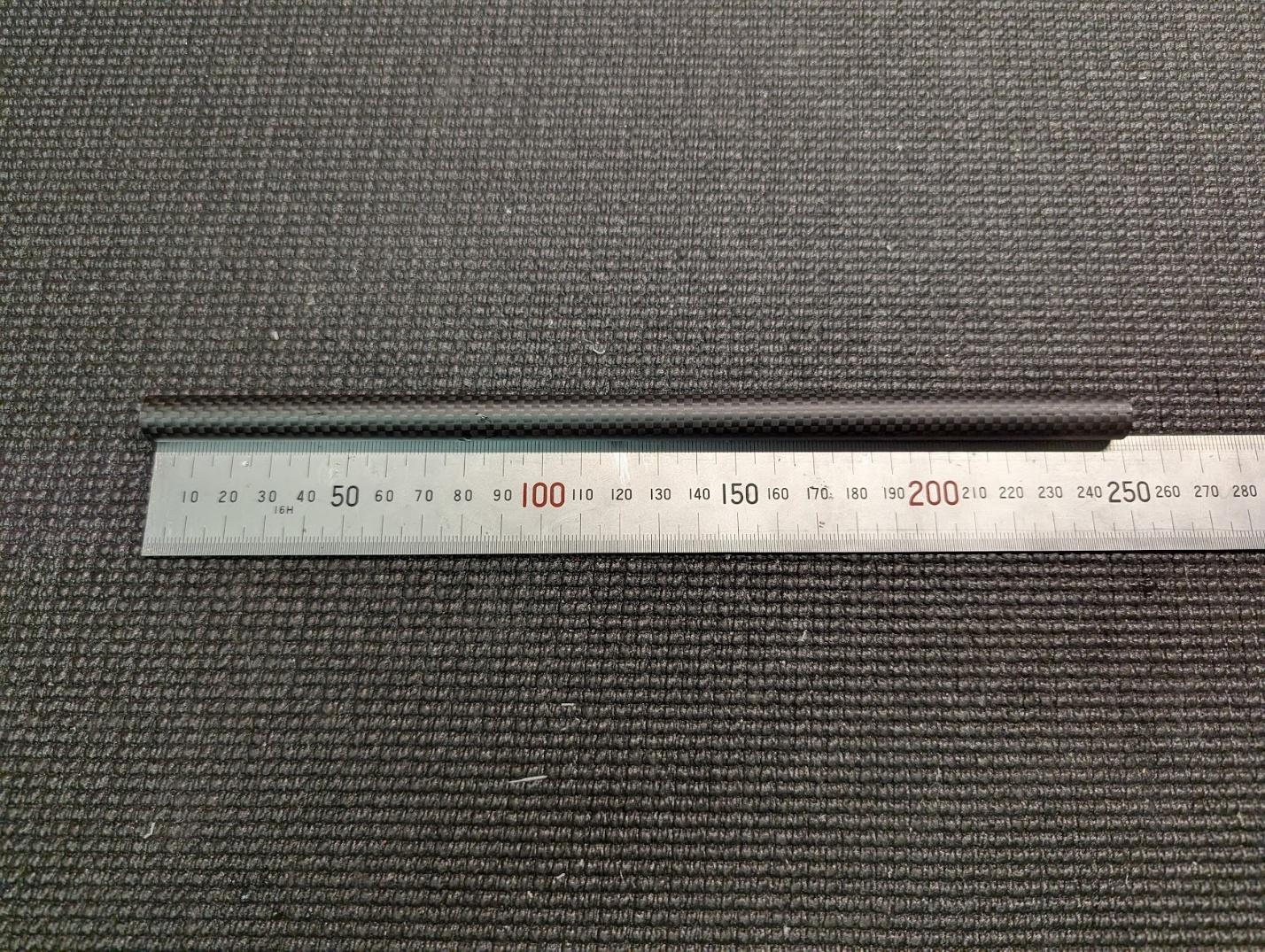
Cut two 248.5mm lengths of 12mm carbon fiber tube for the main struts.
-
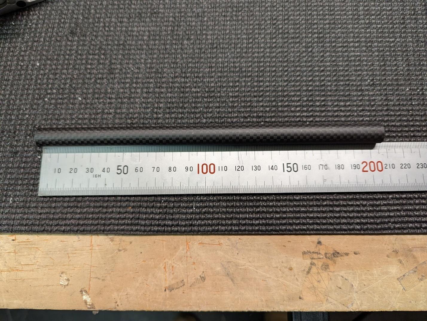
Cut one 205mm length of 12mm carbon fiber tube for the nose strut.
-
Install M3 heat-set threaded inserts into the strut mounts.
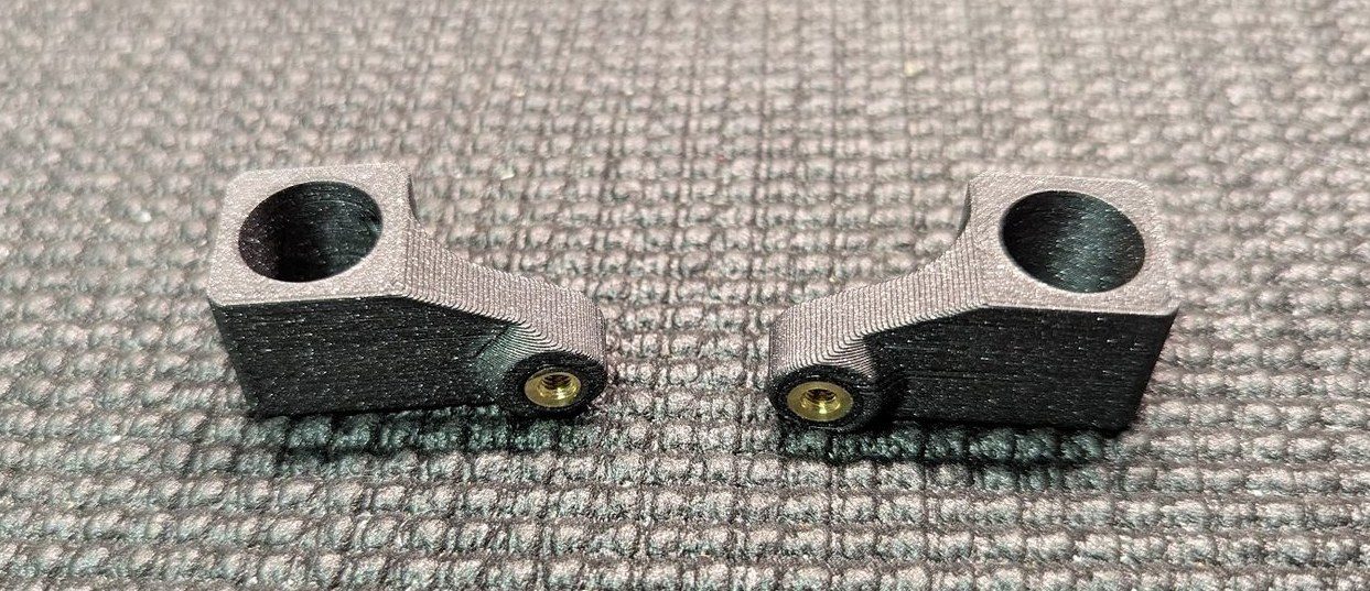
-
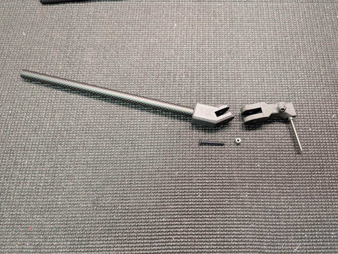
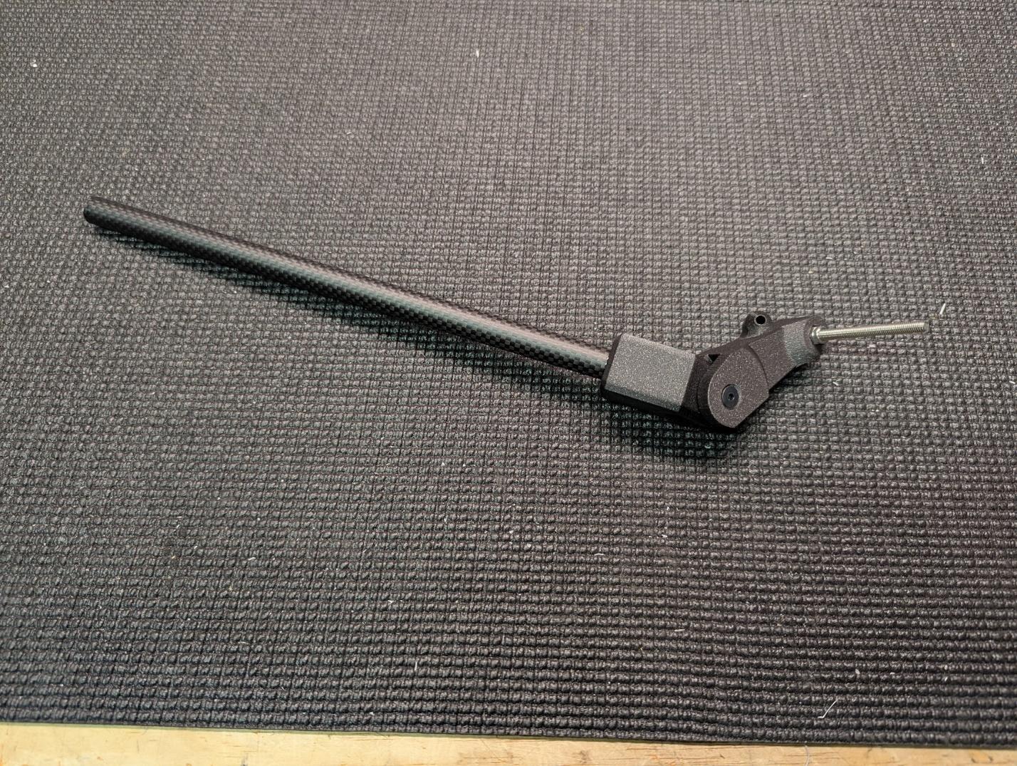
Glue the main gear joints to the carbon main gear struts with CA.
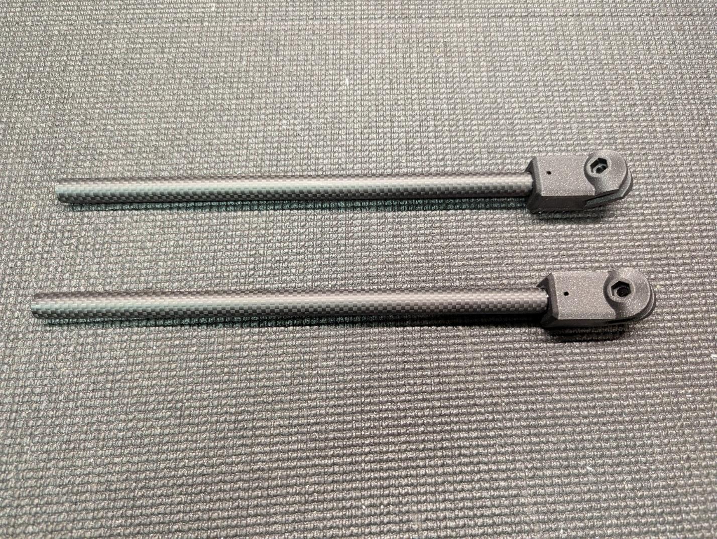
-
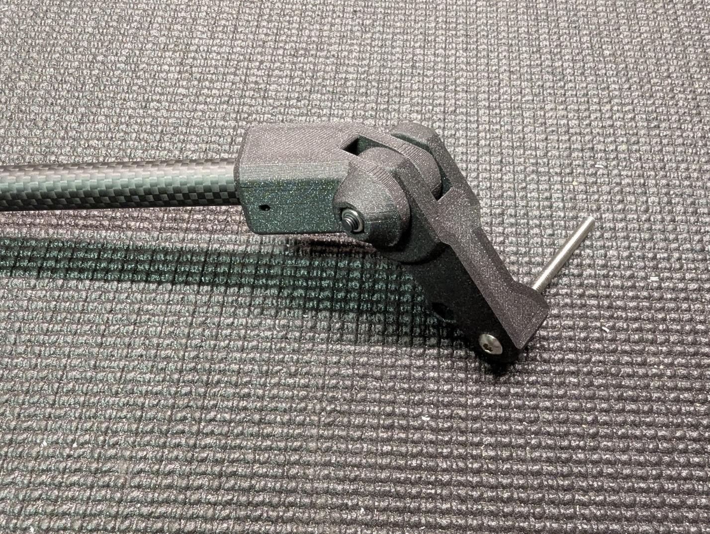
Create the main gear axles using M4 x 60mm bolts and locknuts.
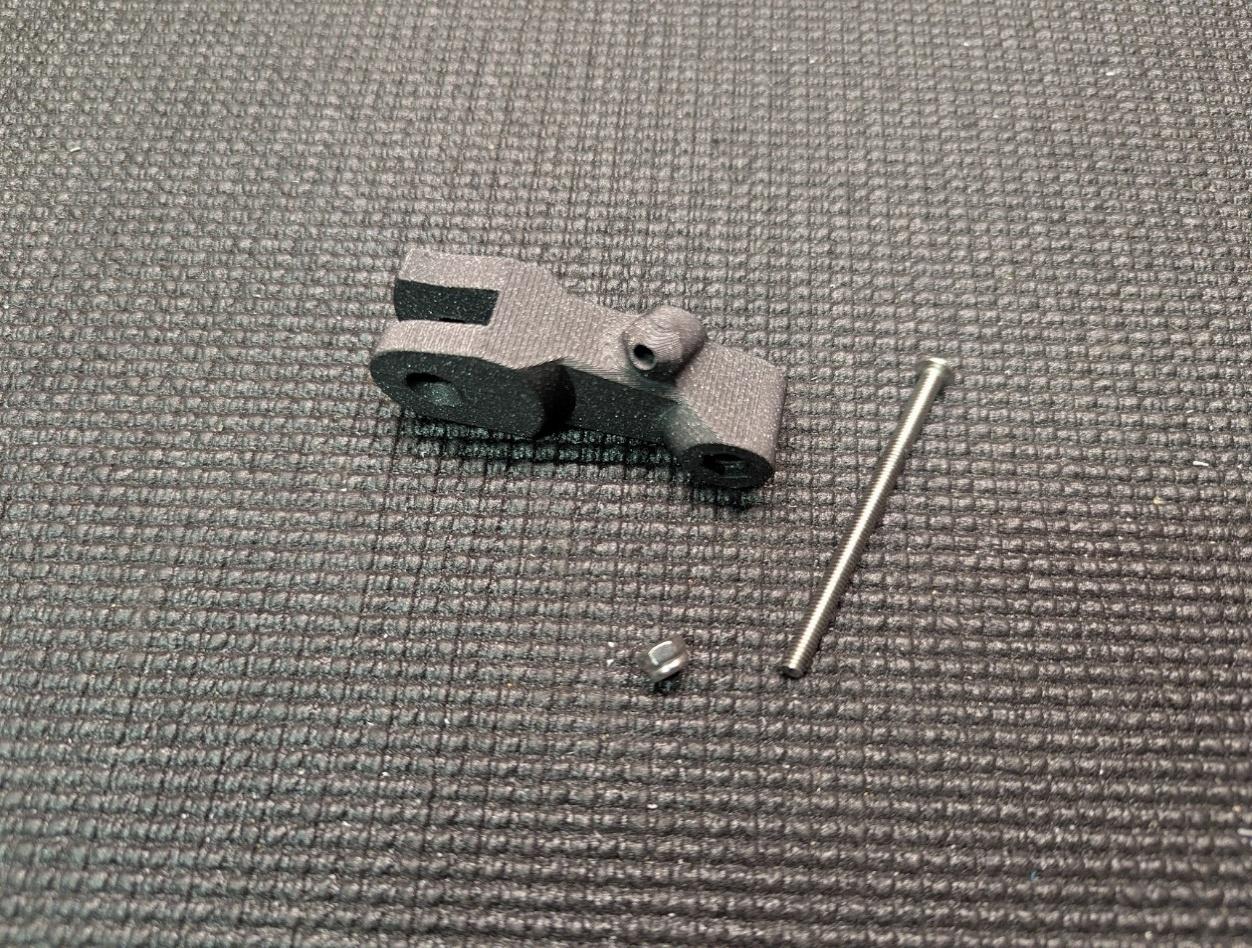
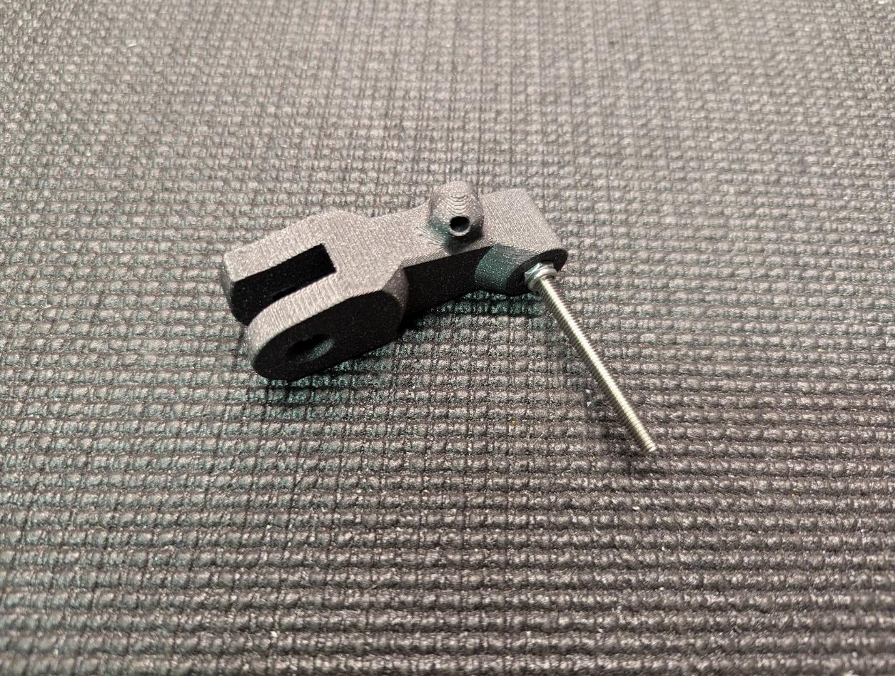
-
Mount the main gear arms to the joints using M4 x 30mm flat-head bolts and locknuts. Tighten them fully, then back off until the arms can pivot freely without slop.
-
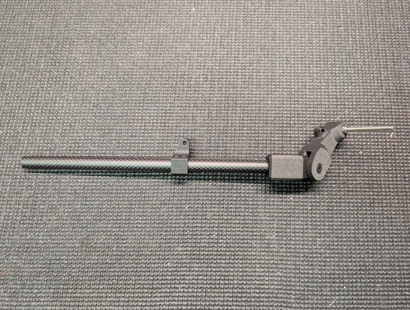
Slide the strut mounts onto the main gear tubes, paying attention to orientation. Do not glue them.
-
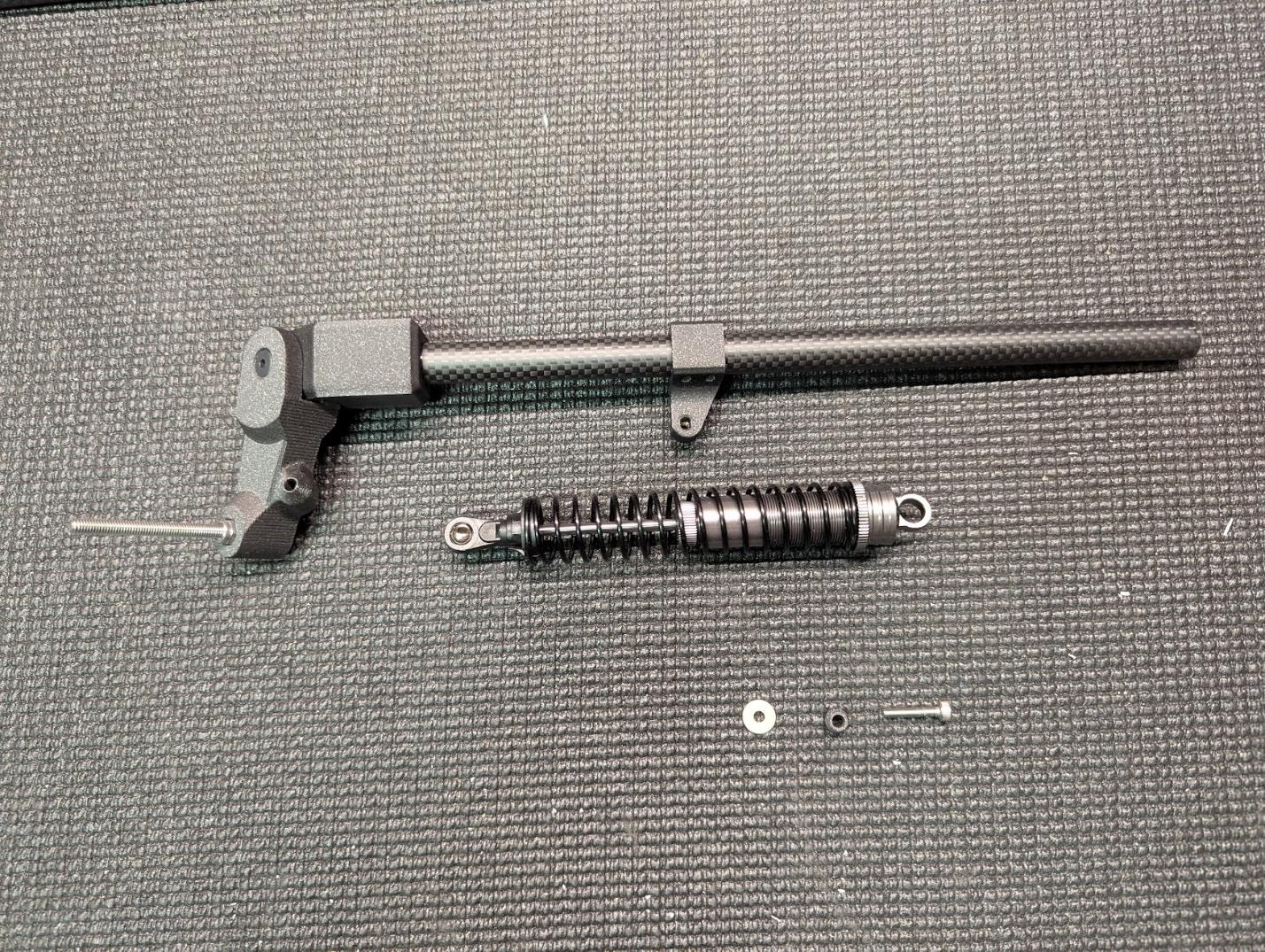
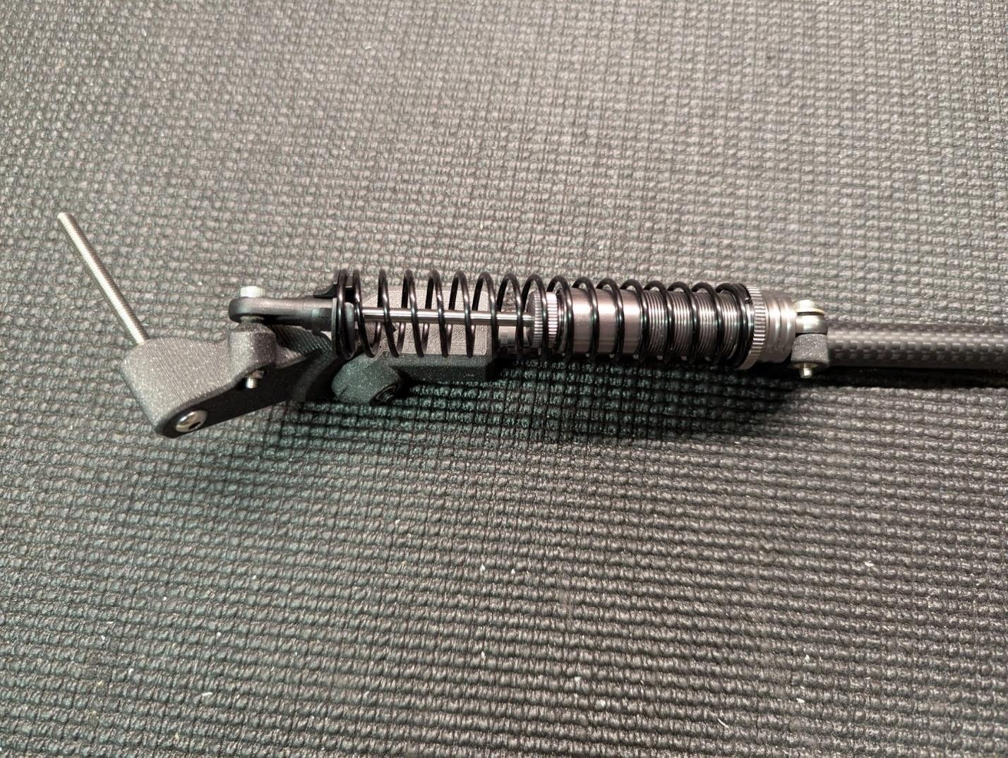
Prepare the shock absorbers along with M3 x 16mm cap screws, low-profile washers, and the printed spacer balls.
-
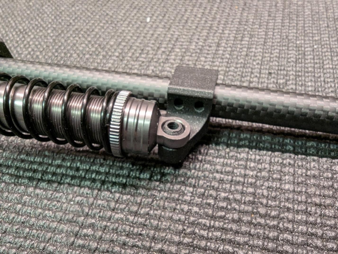
Insert the spacer balls into the top eye of the shock absorbers and align with the strut mounts.
-
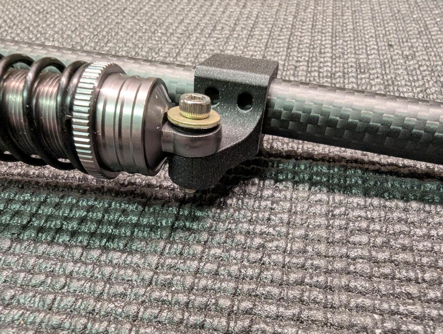
Secure with the M3 x 16mm cap screw and low-profile washer as shown.
-
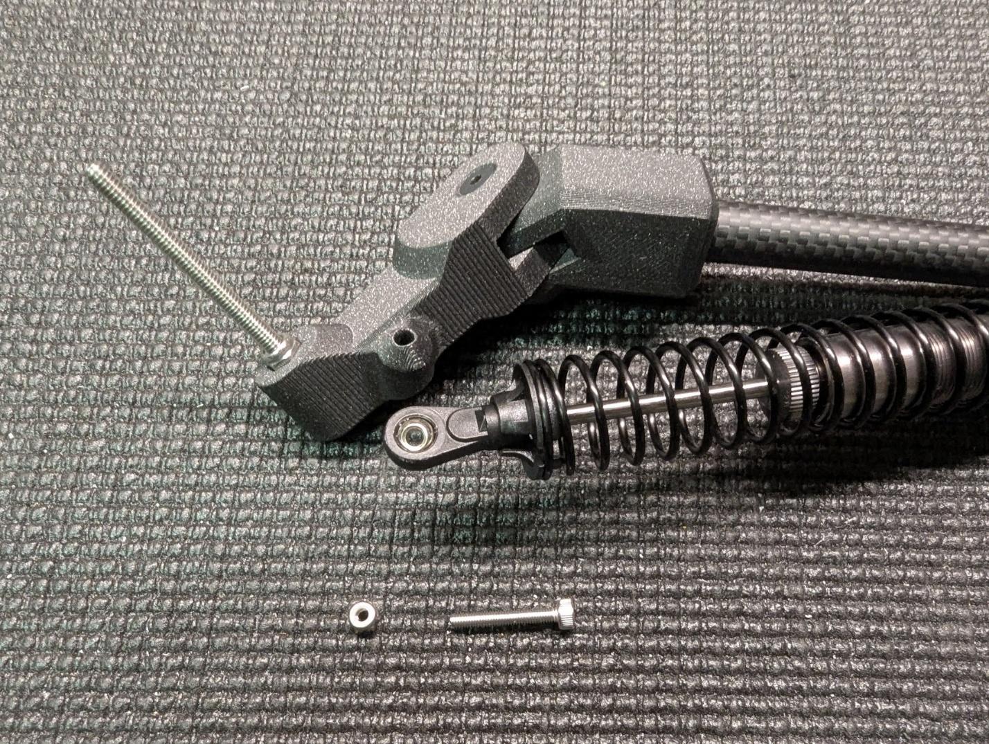
Secure the lower ends of the shock absorbers to the main gear arms using M3 x 20mm cap screws and locknuts.
-
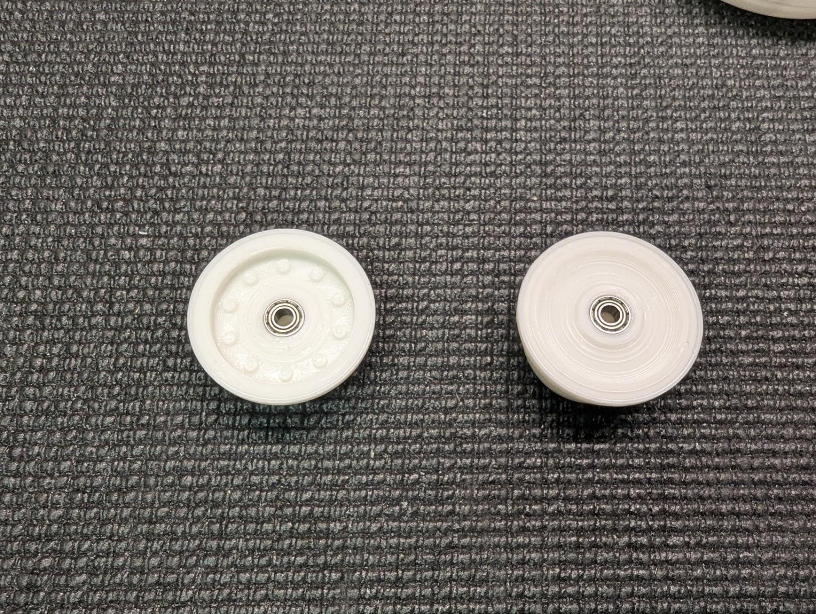
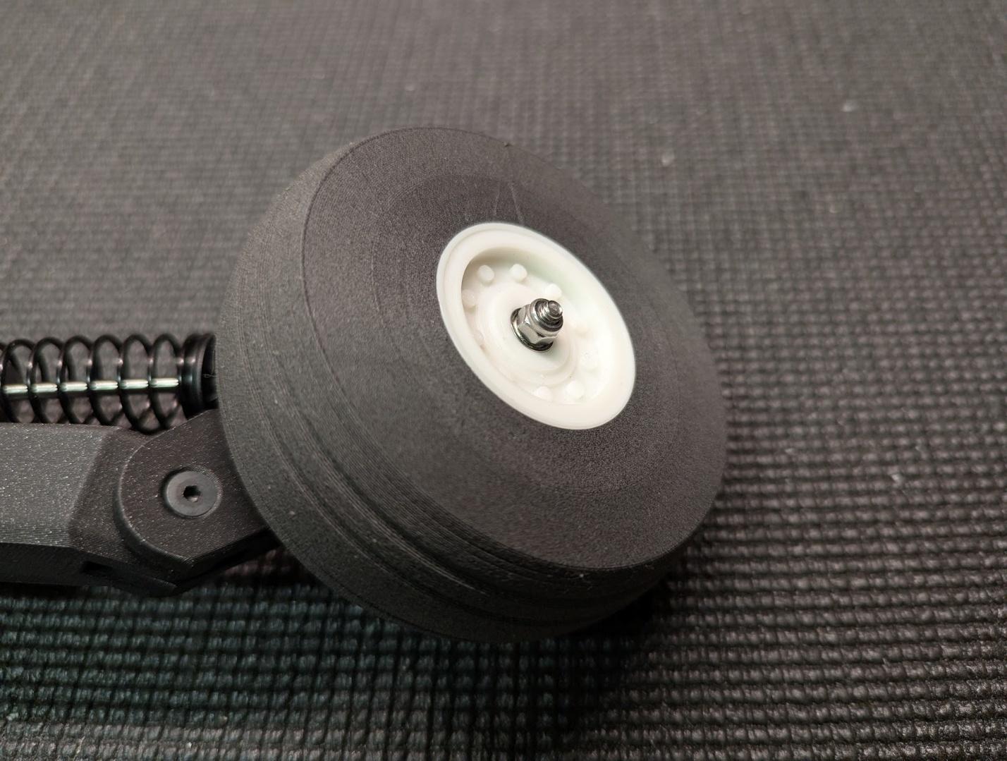
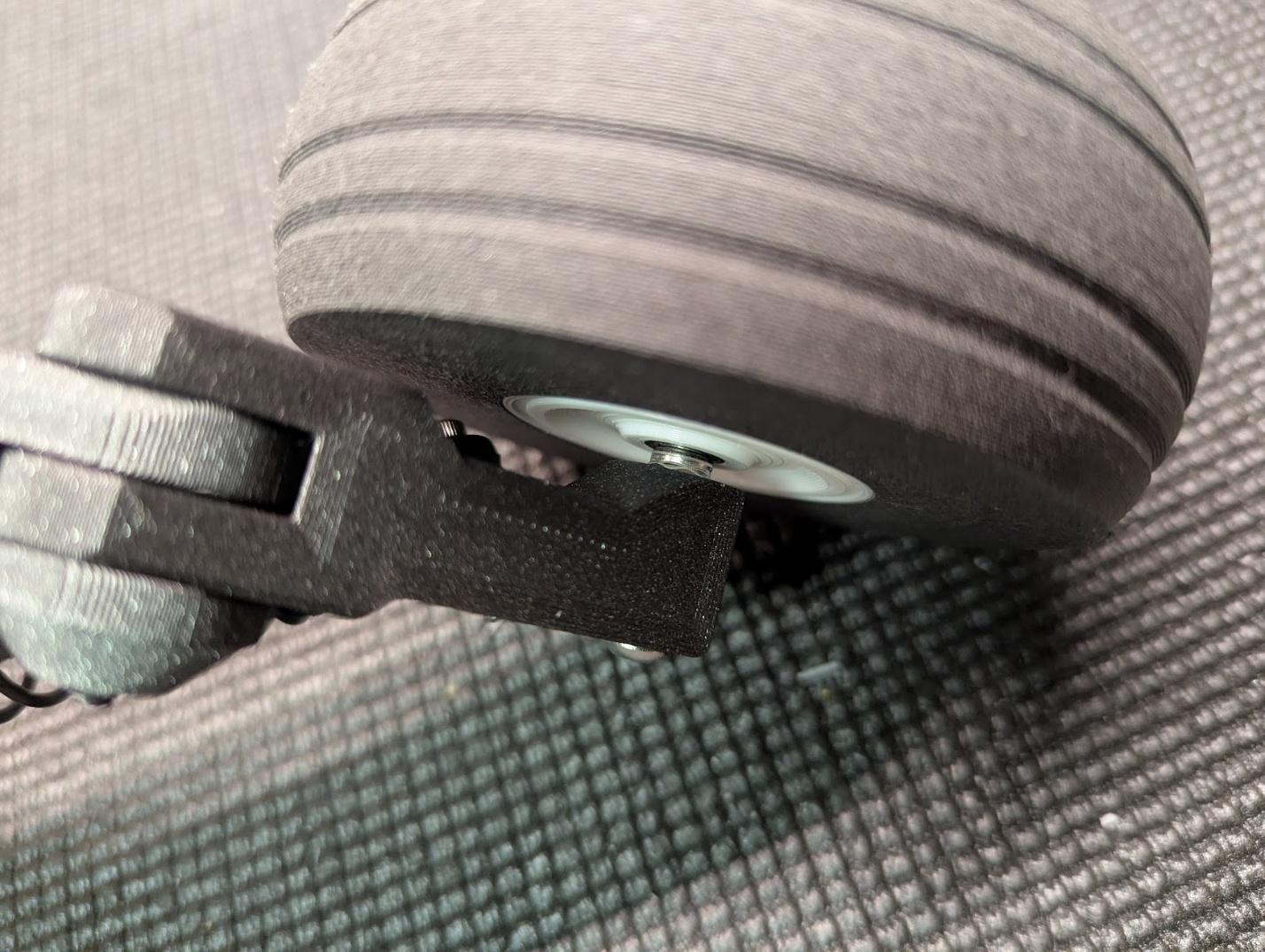
Press the wheel bearings into the main wheel hub parts.
-
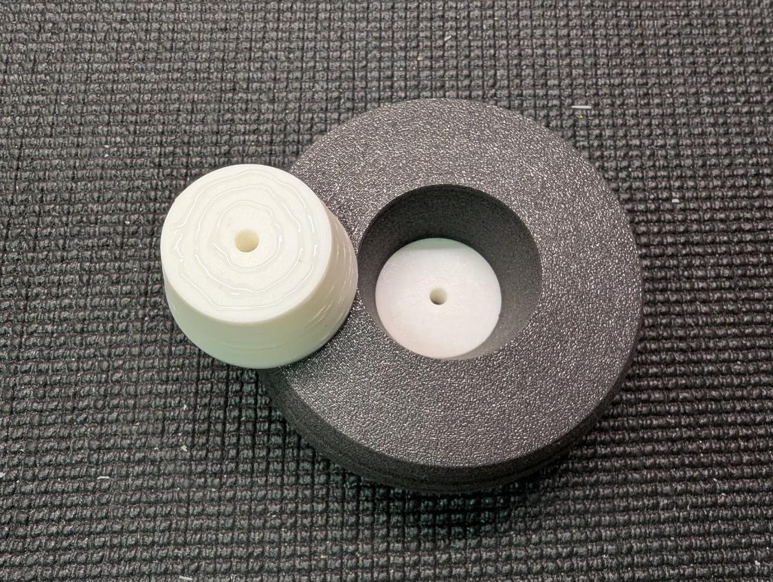
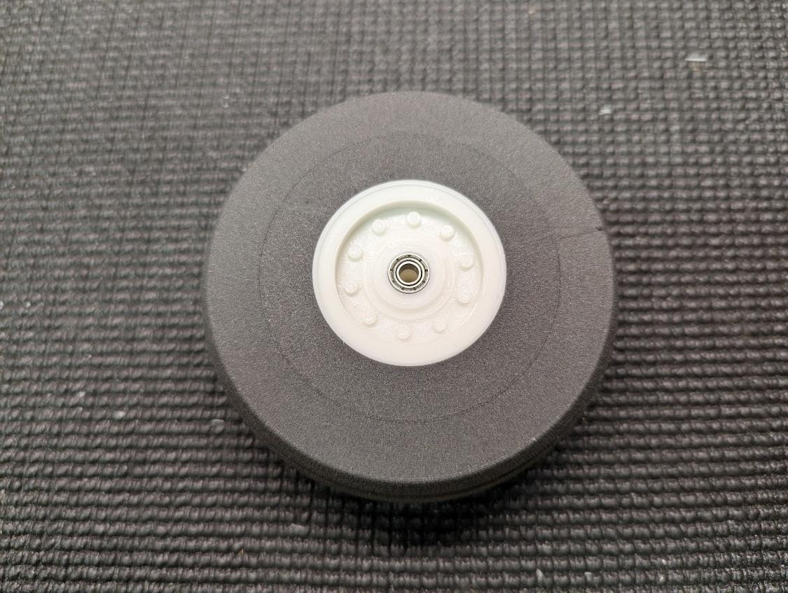
Assemble the main wheels, gluing the two hub components together at the middle. It is not necessary to glue the hubs to the tires.
-
Mount the main wheels to the axles using M4 locknuts.
-
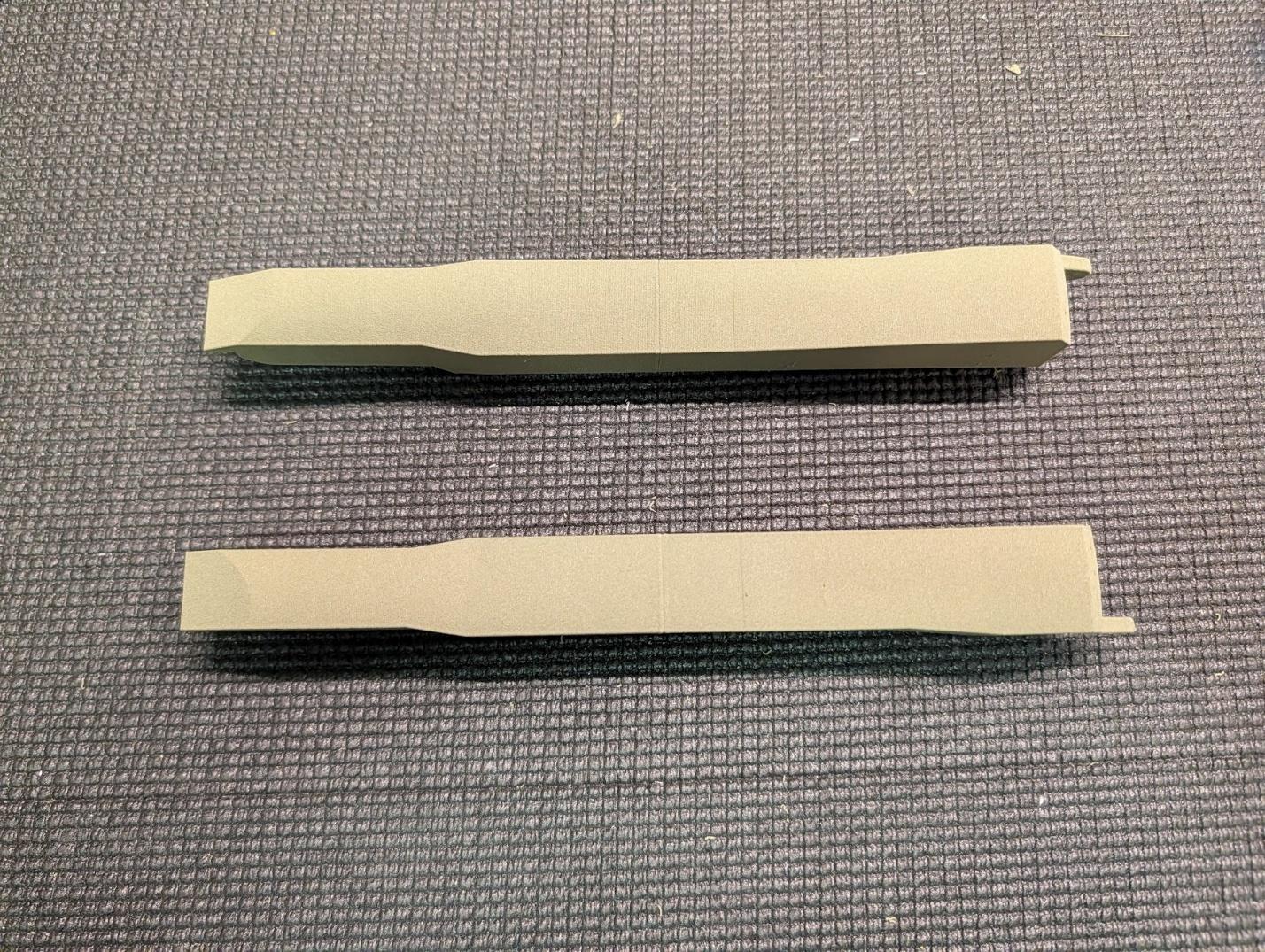
Glue together the sections of the main gear fairings.
-
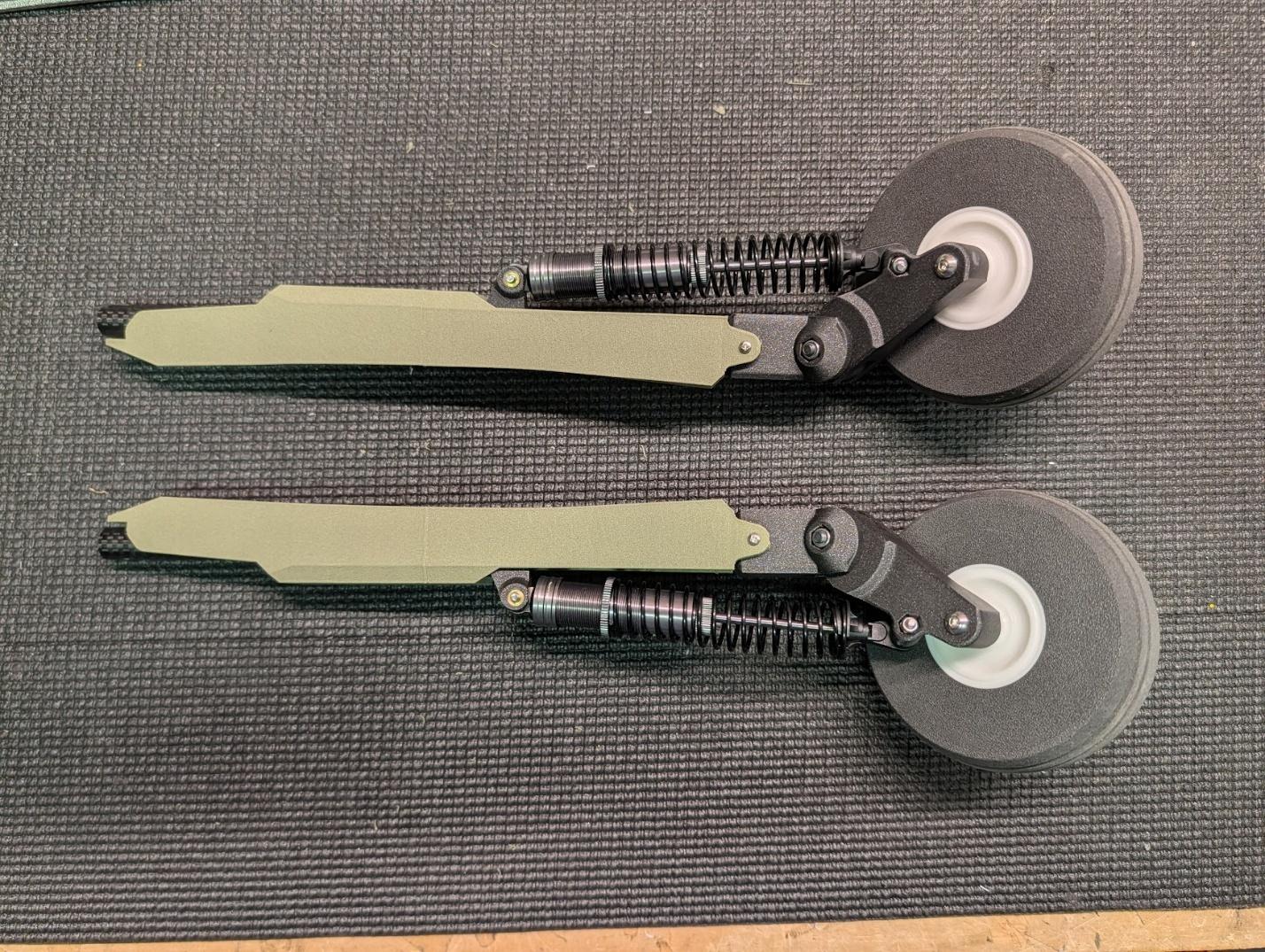
Slide the fairings onto the main gear assemblies and secure them to the joints with #2 x 3/8" self-tapping screws.
-
Now that the fairings have set the correct spacing and alignment of the printed strut mount parts, drop some CA into the two holes to secure them to the main gear tubes.
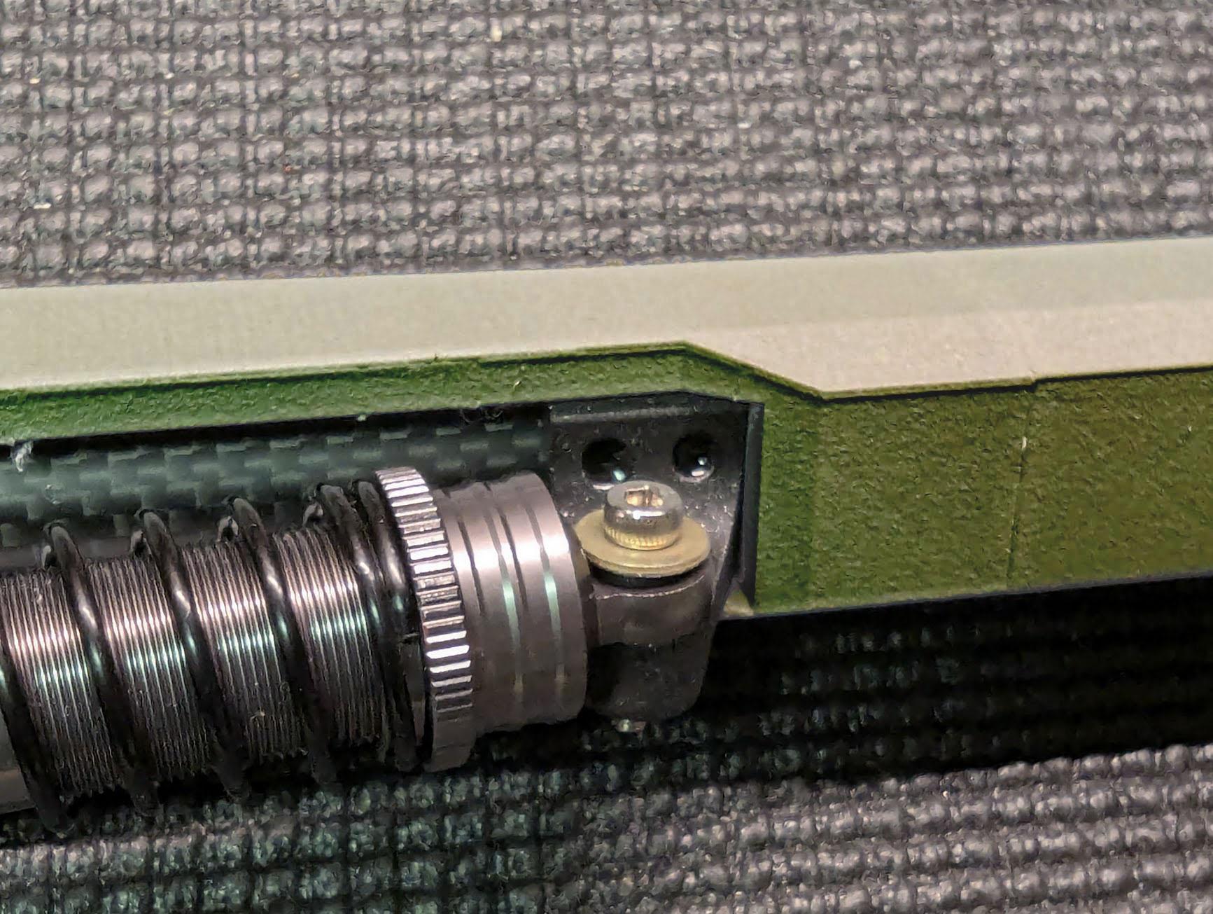
-
Glue the strut reinforcement cylinders into the main strut tubes with CA or epoxy. They should be flush with the ends that insert into the retract units.
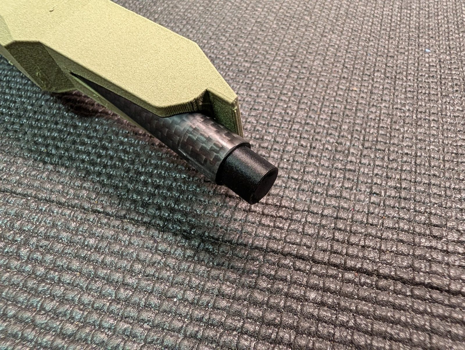
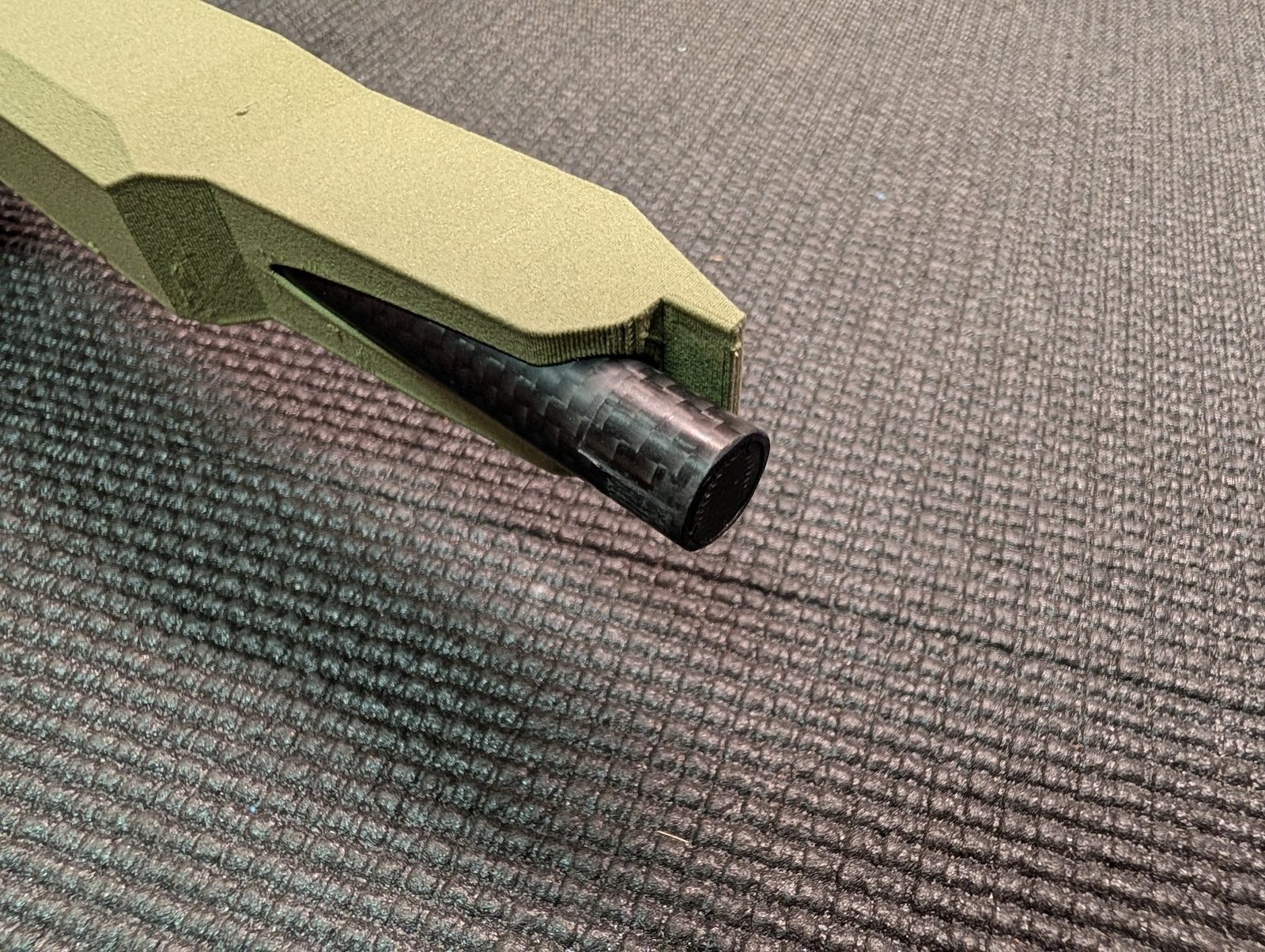
-
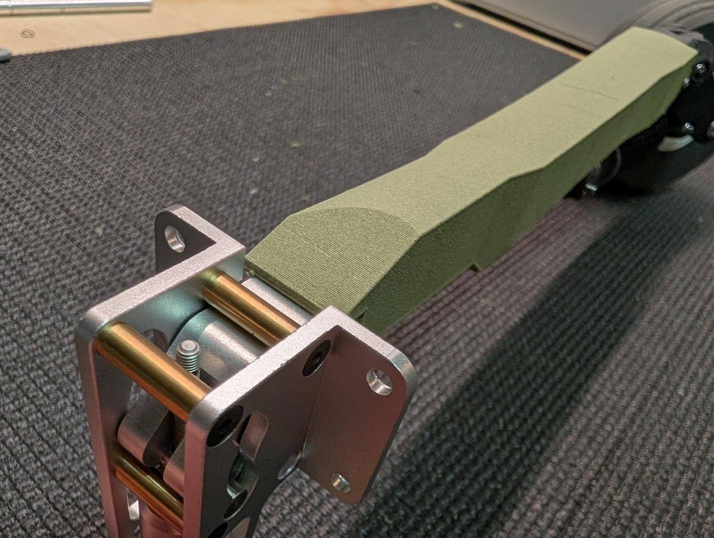
Loosen the screws in the trunnions of the retract units, then slide in the main gear assemblies.
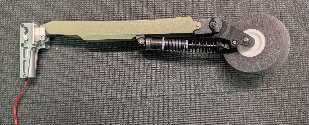
-
The flat portion at the top of the fairings will sit on the outer face of the trunnion, setting the proper alignment of the main gear assembly. Ensure that this interface is not twisted, then tighten the screws on the trunnions to secure the main gear assemblies in place.
-
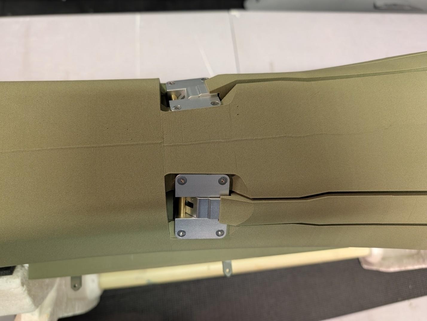
Mount the main gear to the fuselage with eight M3 x 12mm flat head screws. It may be easier to retract the units before screwing them into place.
-
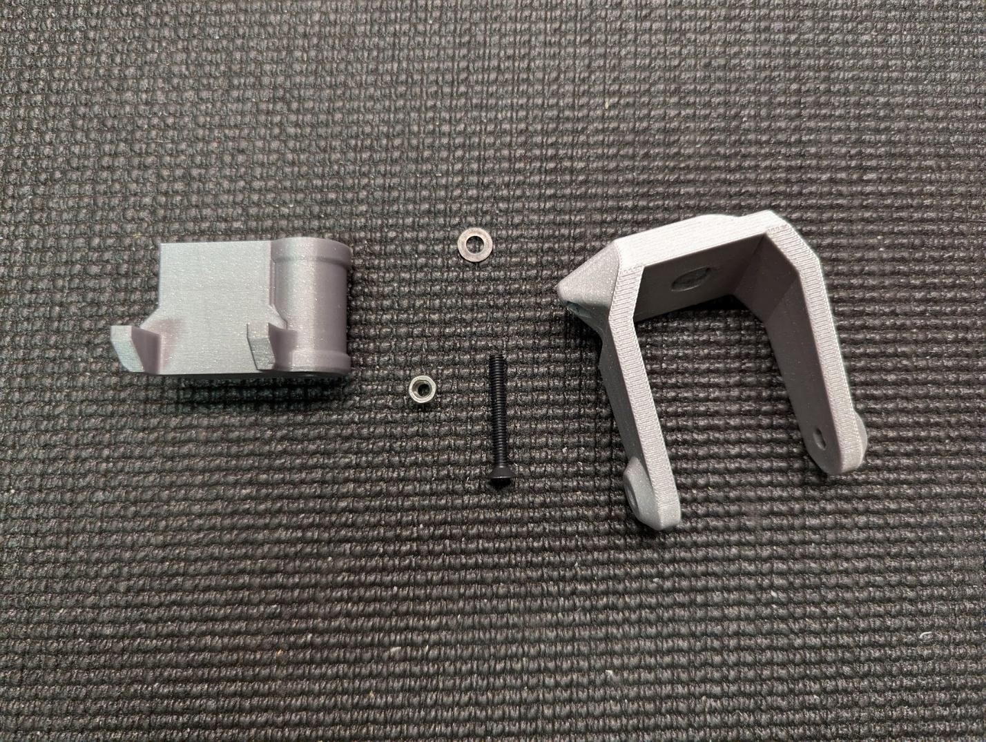
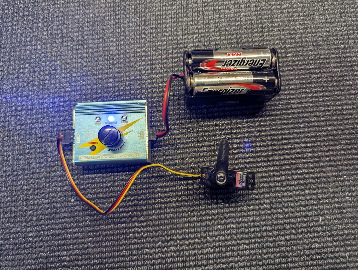
Prepare the nose gear fork, nose gear joint, M4 x 30mm flat head screw, washer, and locknut, and the nose steering servo.
-
Create the nose steering pushrod with some ball ends and a short length of M2 threaded rod.
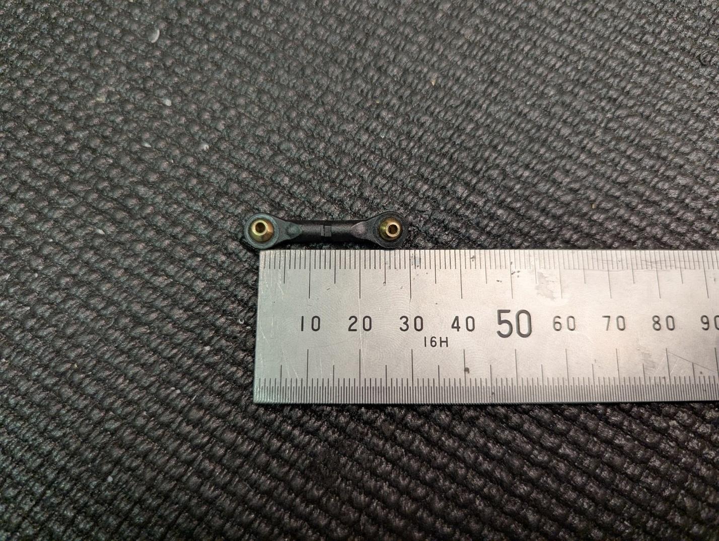
-
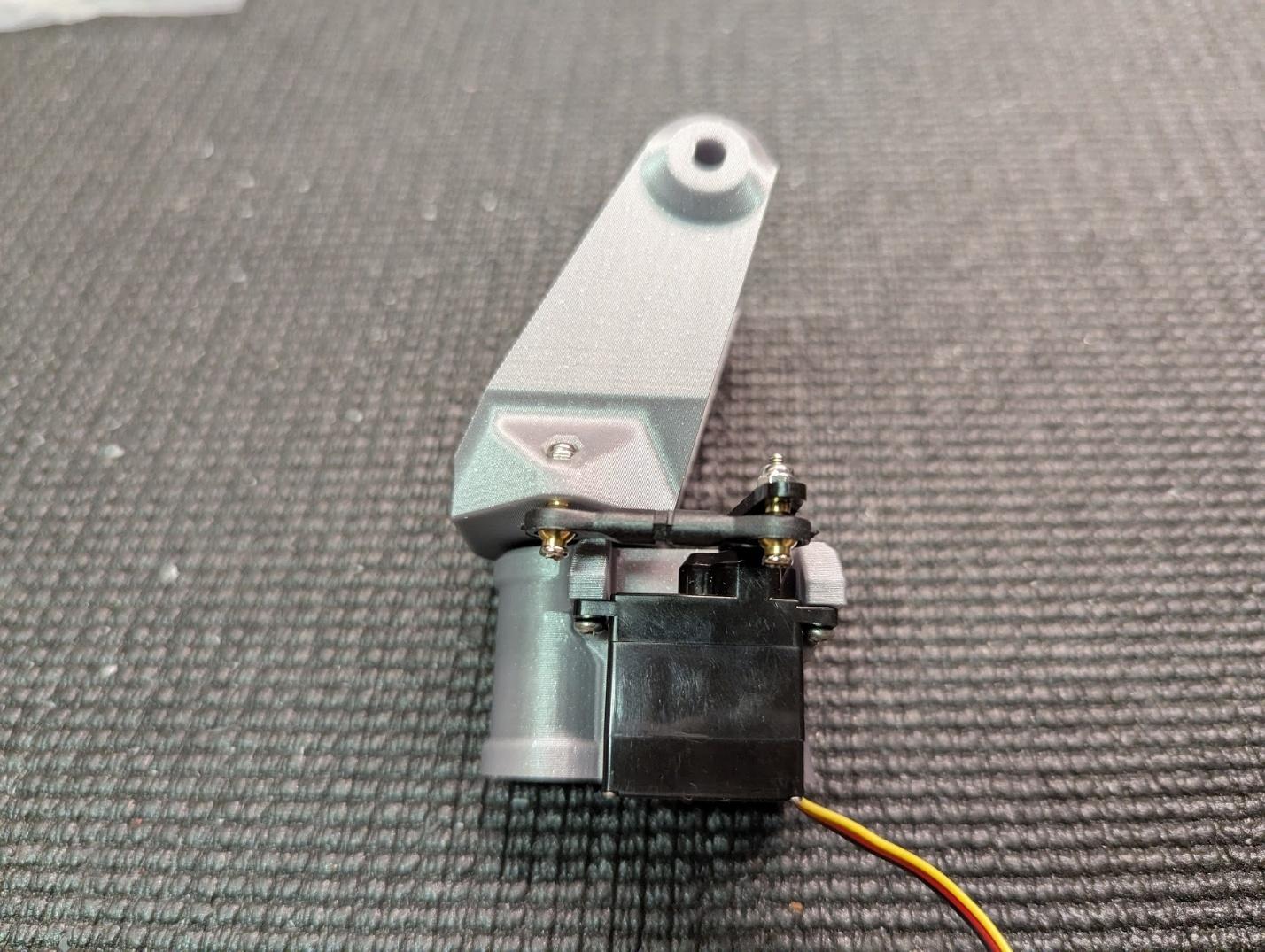
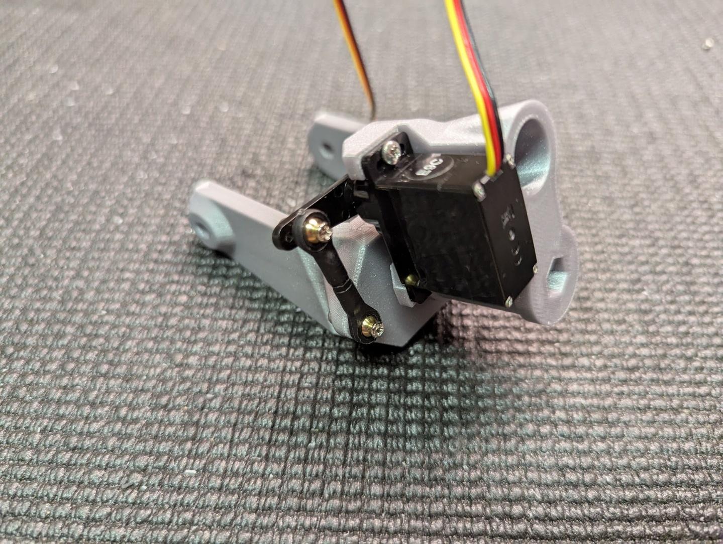
Assemble the parts to form the nose steering assembly. The M4 screw should be inserted from the bottom of the nose gear fork, and the M4 washer should sit between the fork and the joint. Fully tighten the screw and then back off until the fork can move freely without slop. Secure the servo with some #2 x 3/8" self-tapping screws.
-
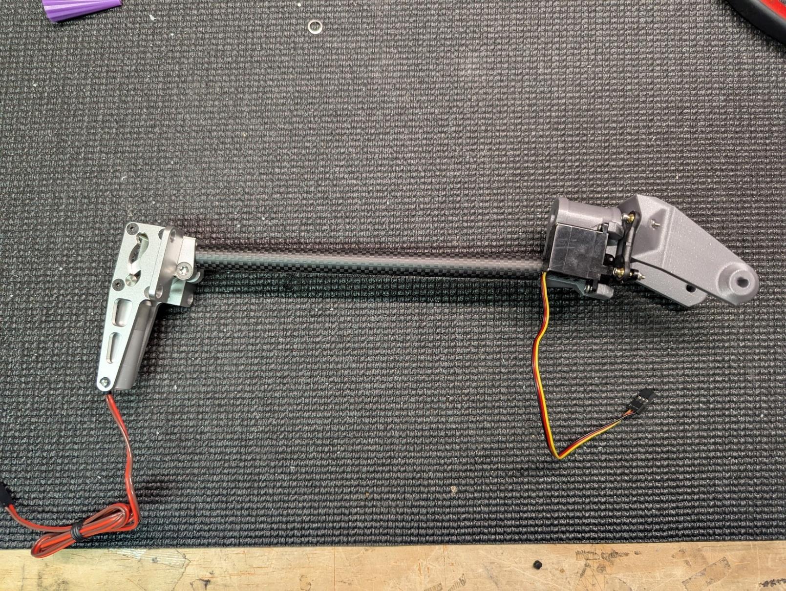
Glue the 205mm nose gear tube into the nose gear joint with CA.

-
Glue a strut reinforcement cylinder into the top of the nose strut tube, flush with the end, then mount the tube to the nose retract unit and tighten.
-
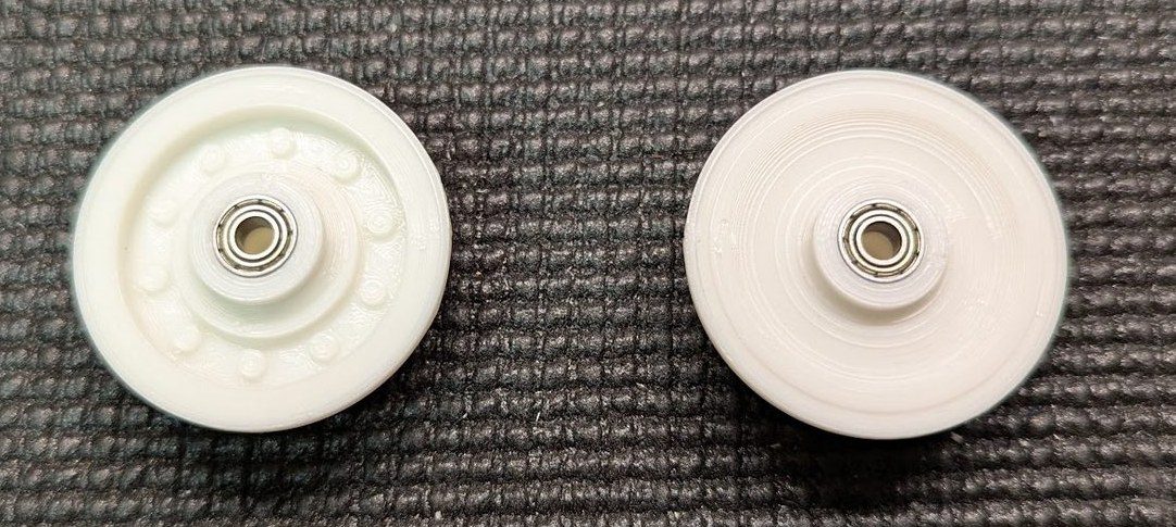
Press more wheel bearings into the nose wheel hubs. Assemble the hubs and tire in the same manner as the main wheels.
-
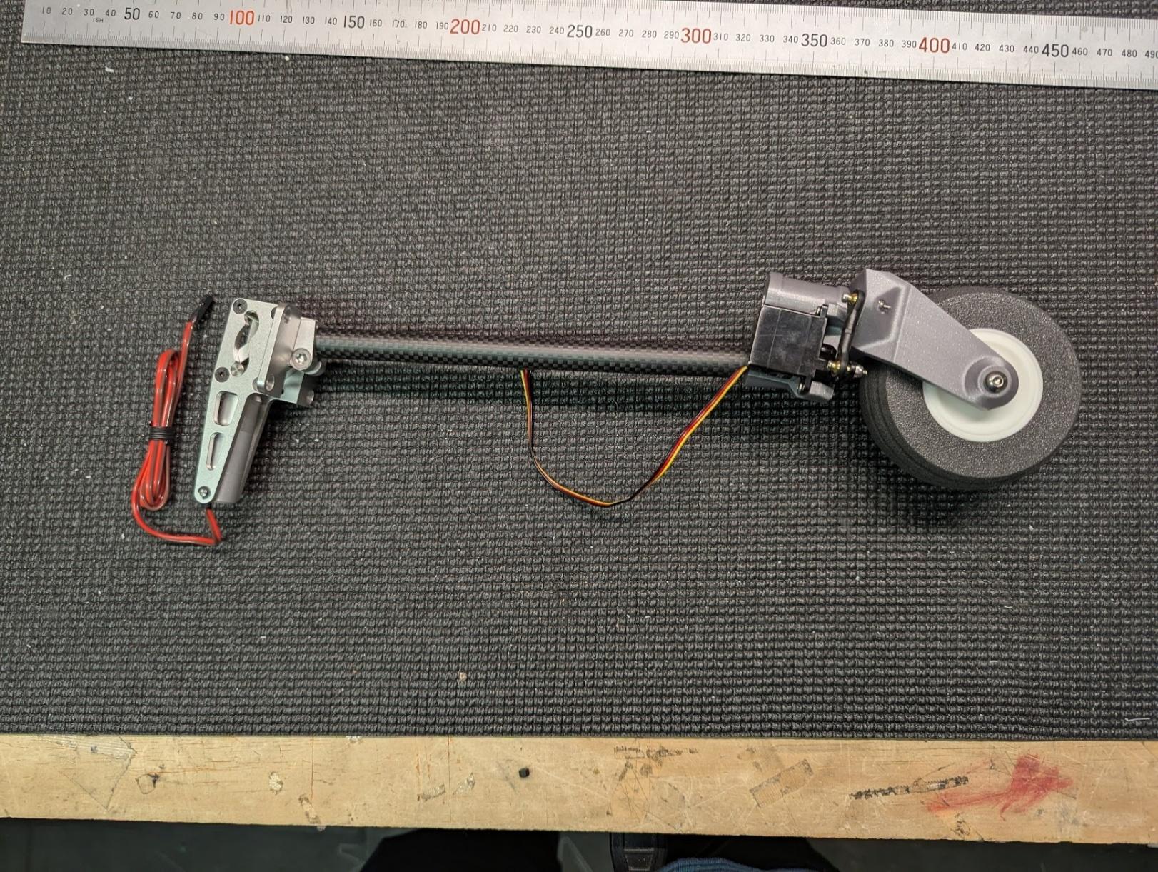
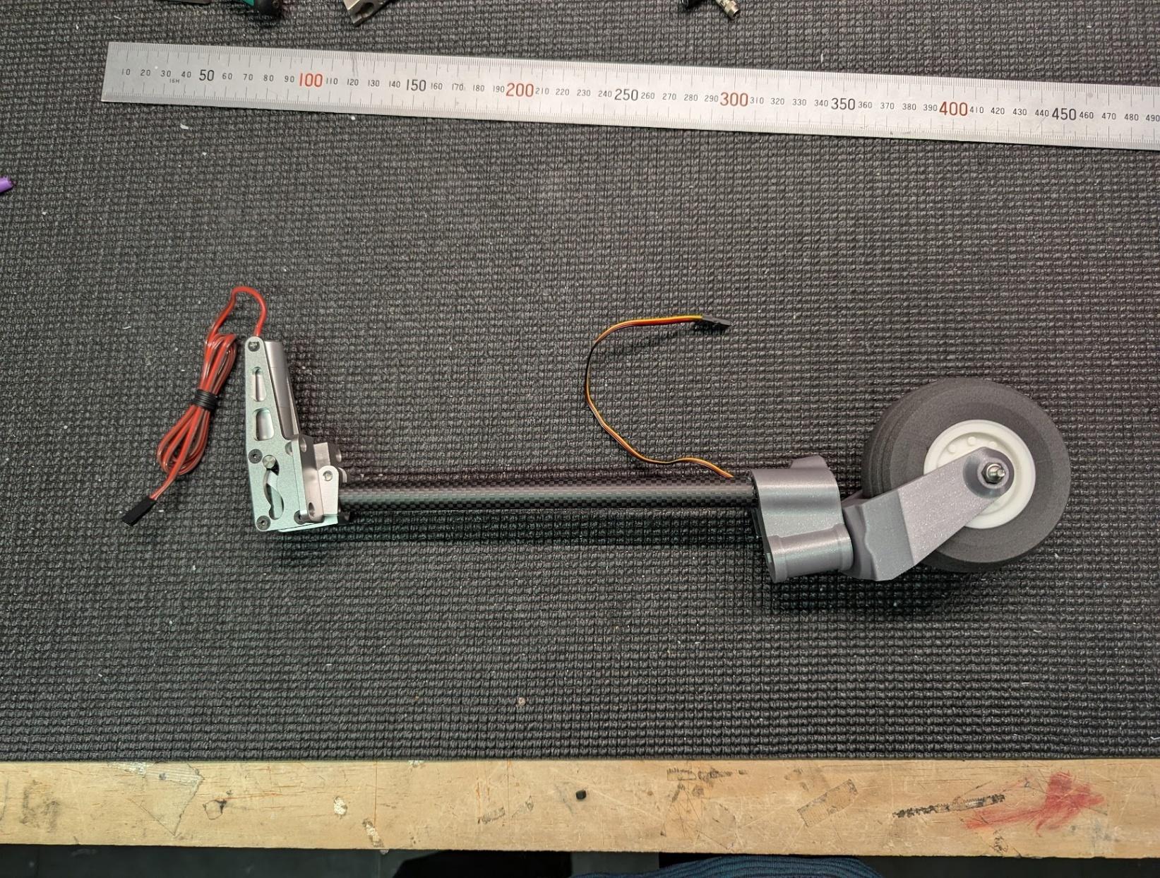
Mount the nose wheel to the fork using an M4 x 60mm screw and locknut.
-
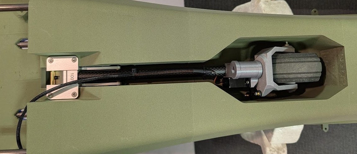
Install the completed nose gear assembly into the fuselage with four M3 x 12mm flat head screws.
-
Secure the lead from the nose steering servo and ensure that there's enough slack for the gear to retract and extend without interference.
Motor and propeller installation
-
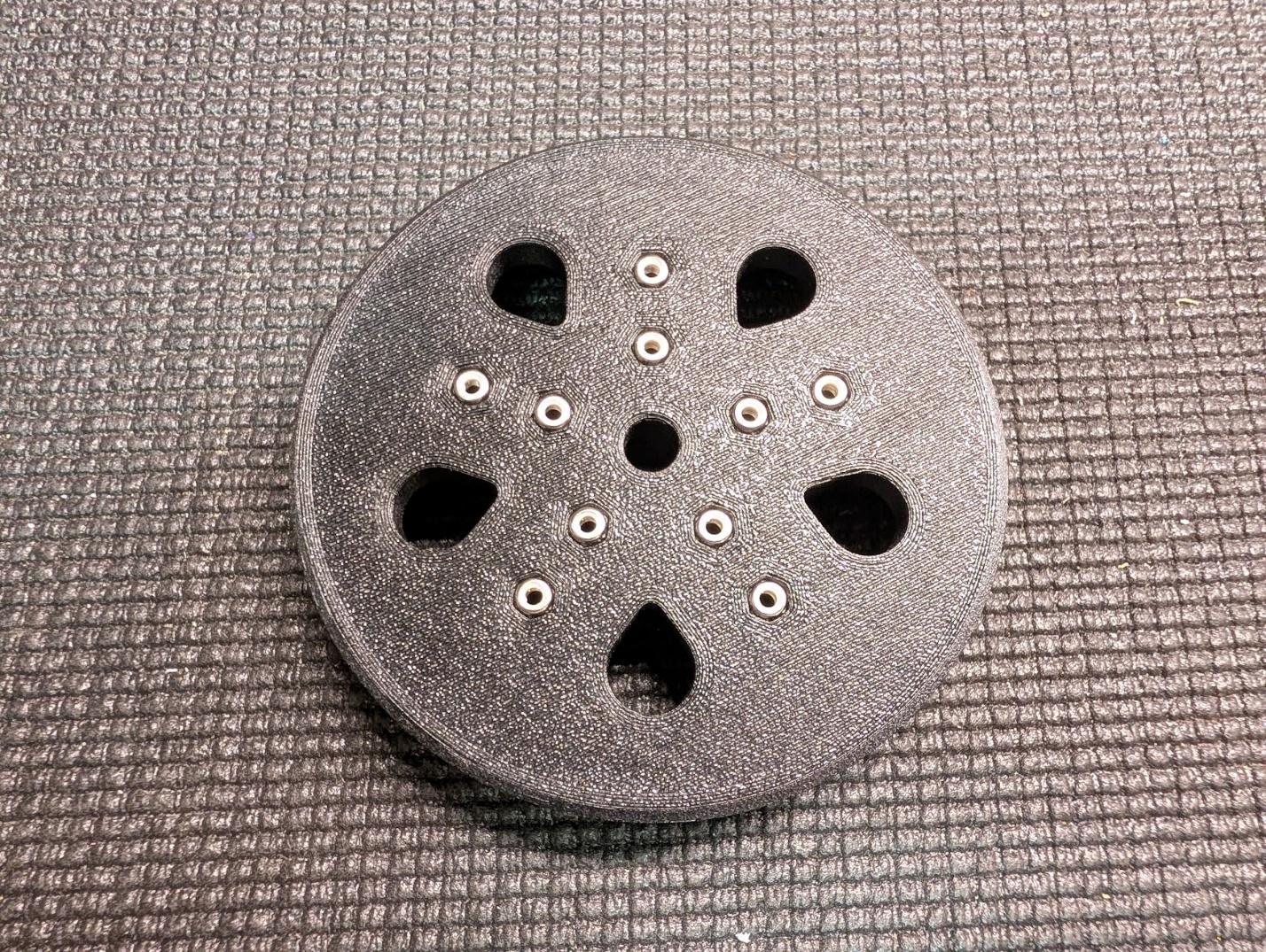
Press M3 locknuts into the back of the propeller hub.
-
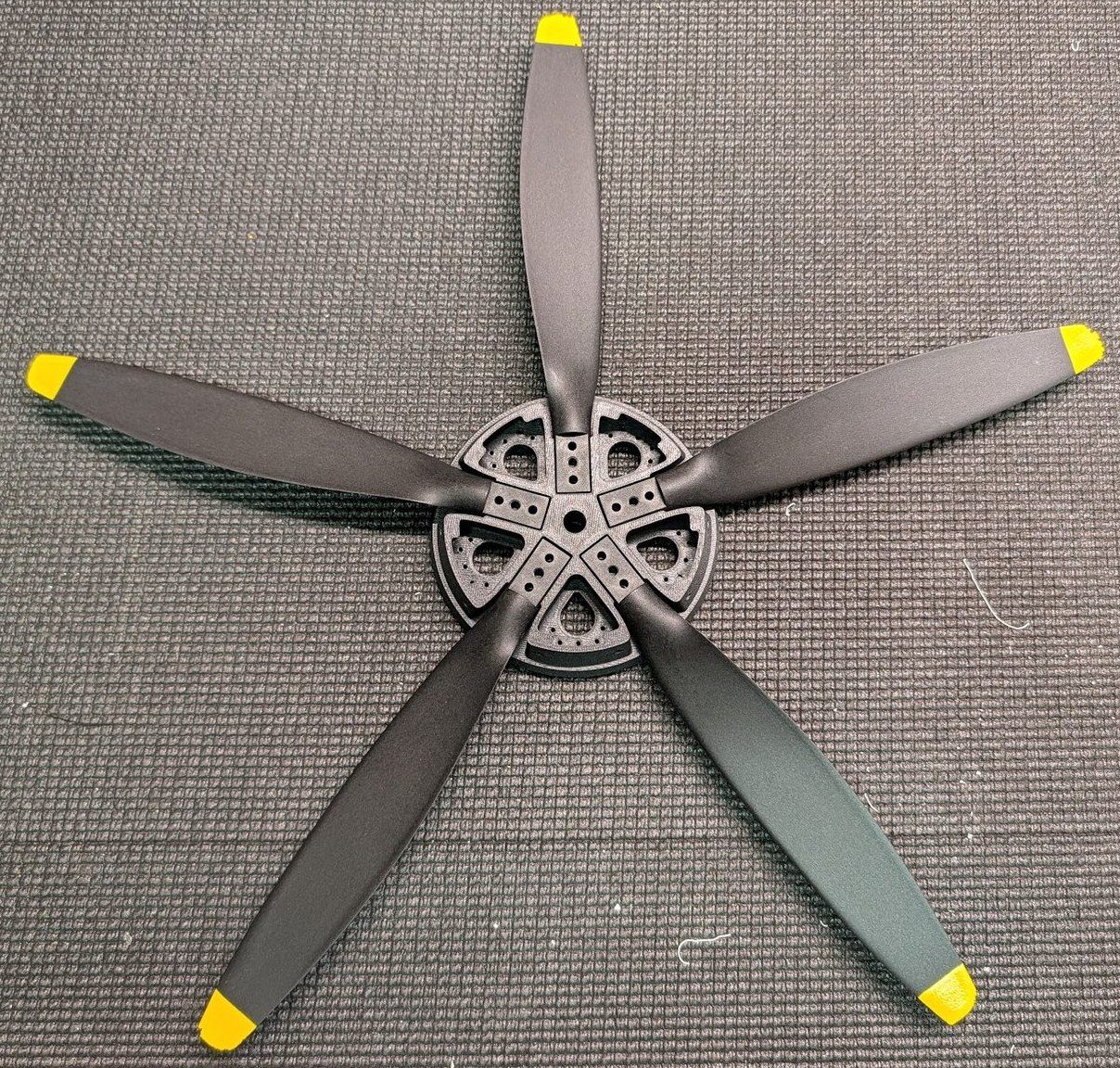
Install the blades into the hub, ensuring the correct orientation. It's a good idea to individually weigh the blades and try to arrange them in as balanced a pattern as possible.
-
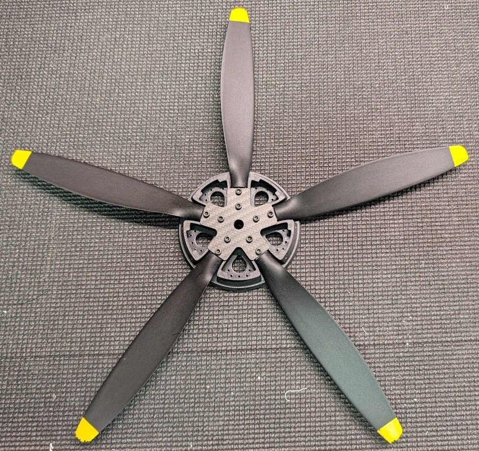
Place the propeller hub plate over the blade roots, then secure with the M3 cap screws included with the propeller blades. If you have the ability, you may choose to CNC cut the plate from fiberglass or carbon fiber rather than printing it. This is also a good time to balance the propeller, which you can do by adding small tapping screws to the small holes around the inside of the hub.
-
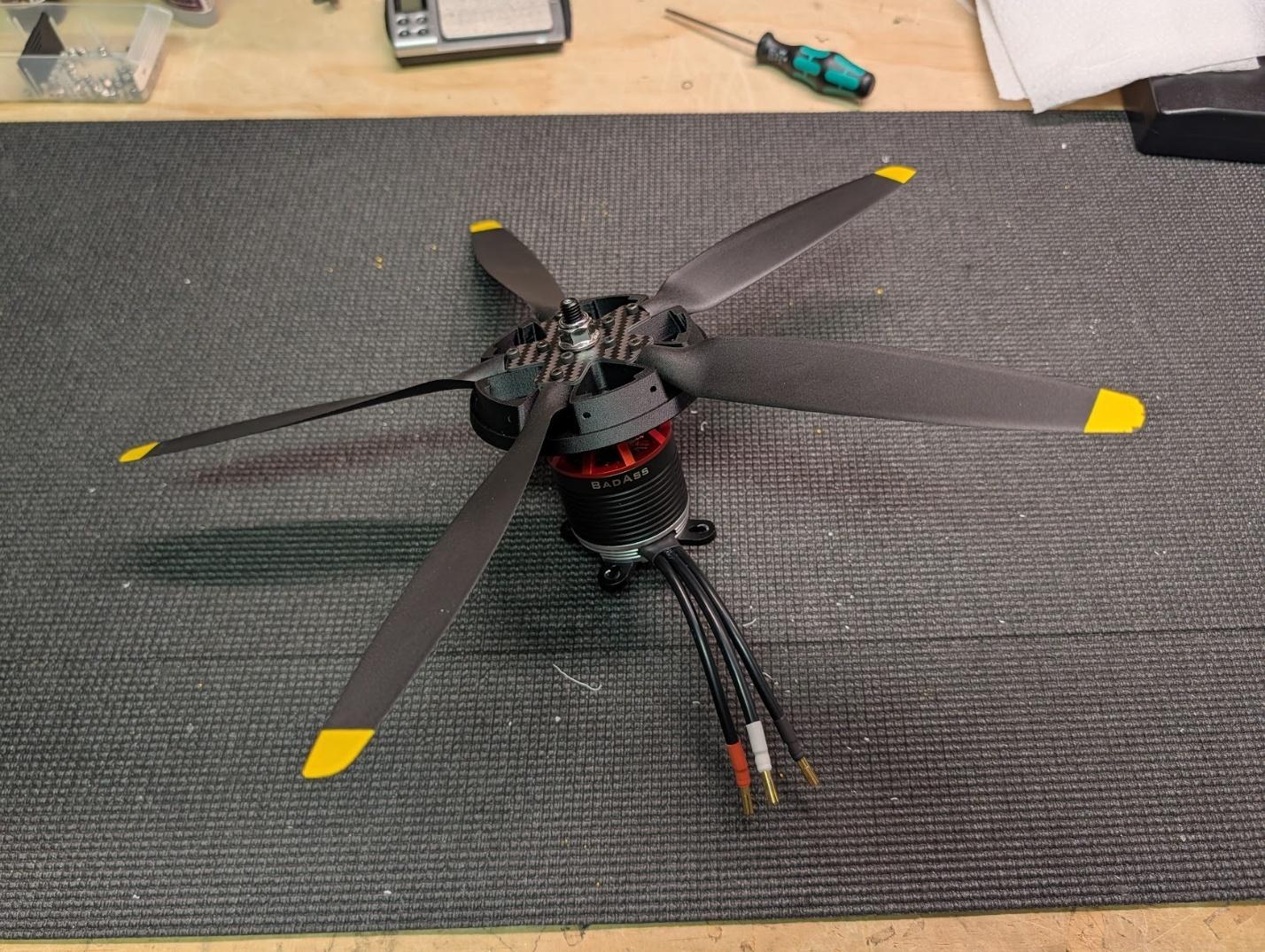
Mount the completed propeller hub assembly to the motor using the locknut included with the motor. It's easiest to do this now because it's difficult to grip the motor when it's installed inside the aircraft. Also, attach the cross mount to the motor during this step.
-
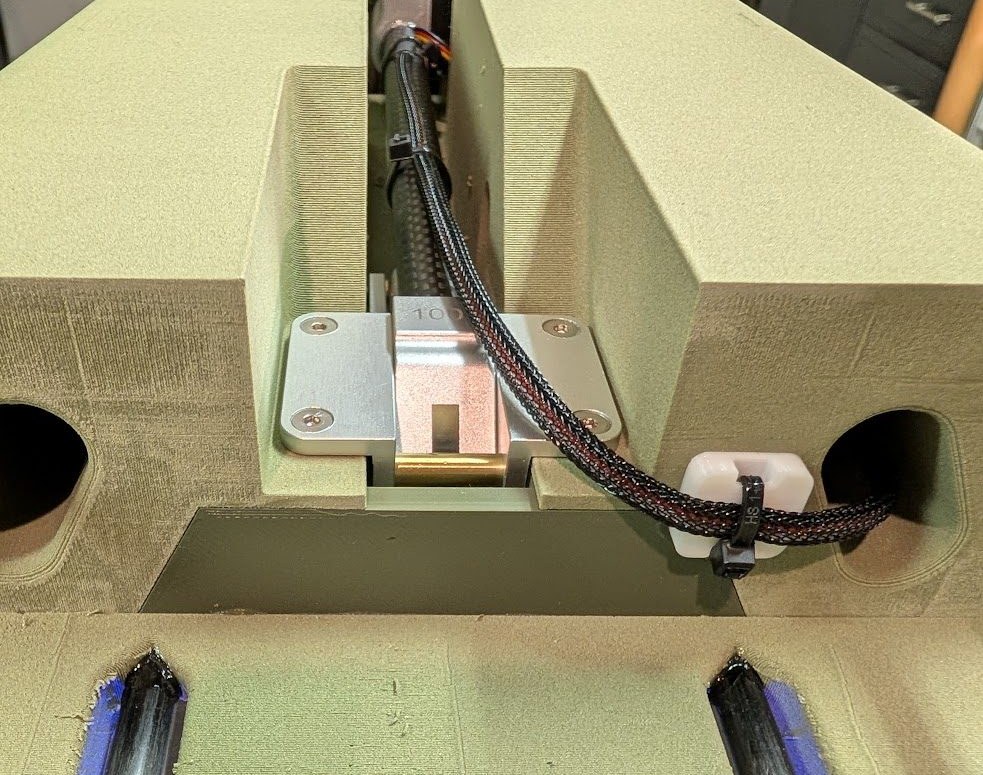
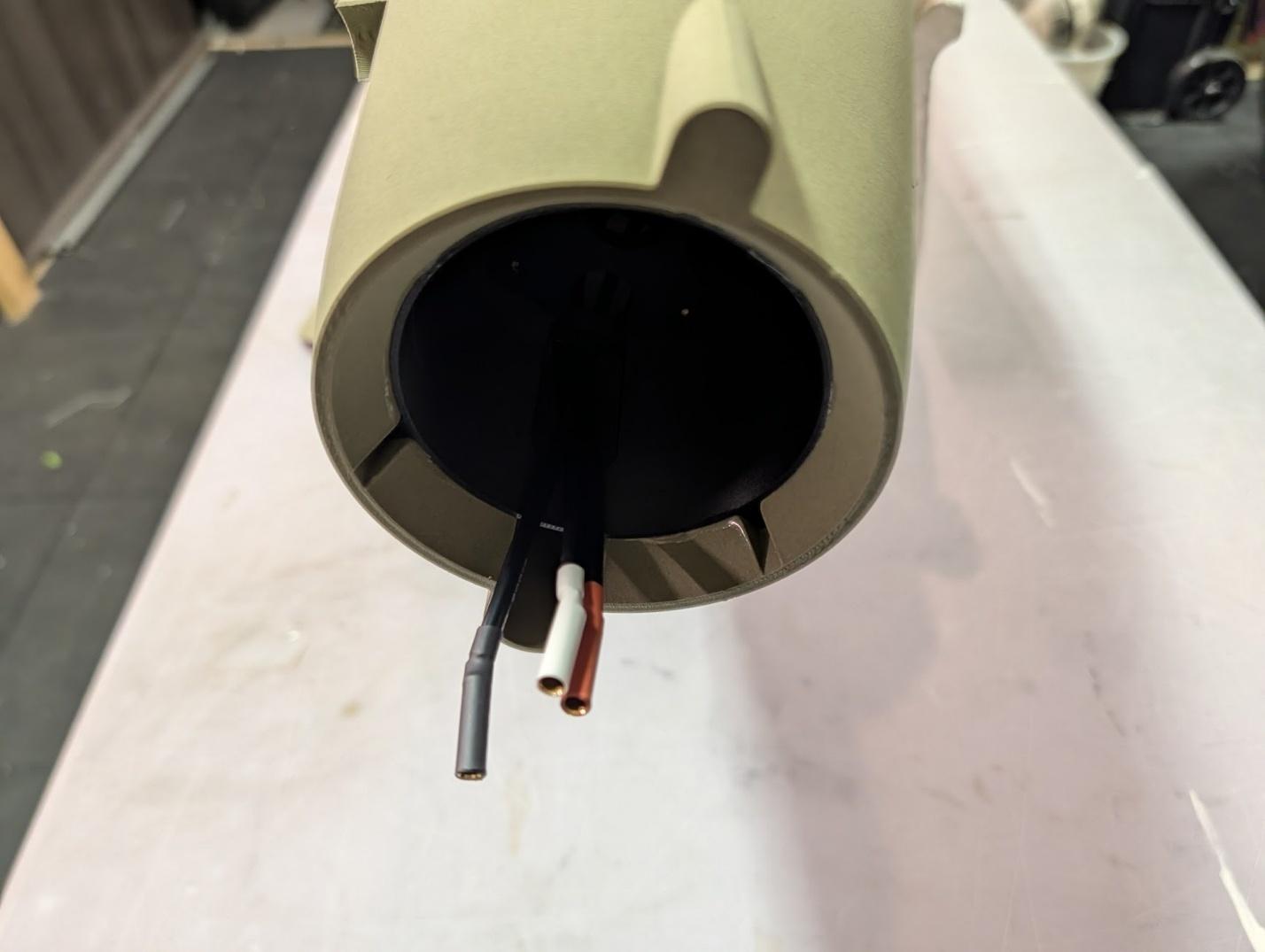
Place the ESC inside the fuselage and pull the wires through the hole in the top of the motor mount. Note that the fuselage is upside down in this photo.
-
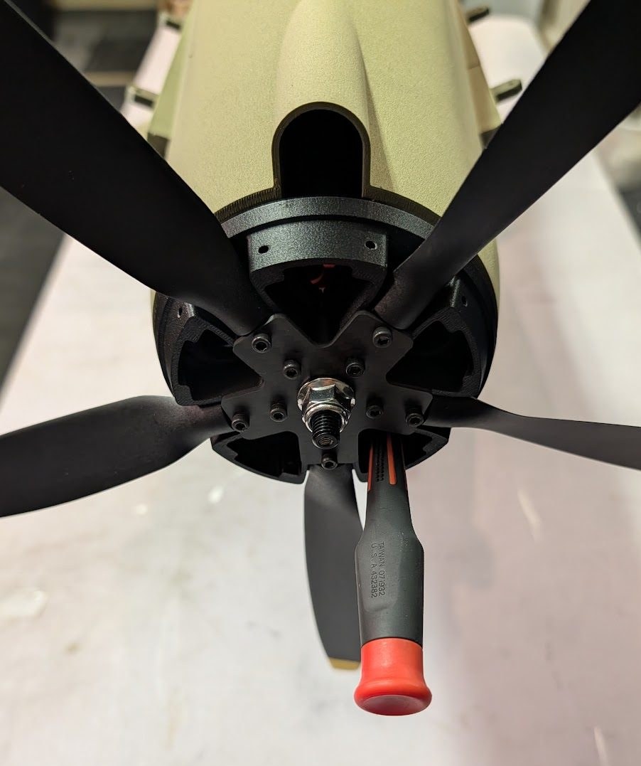
Connect the motor wires and install the motor in the fuselage. Use the large holes in the hub to install and tighten the motor mount screws.
Final assembly and finishing
-
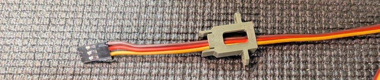
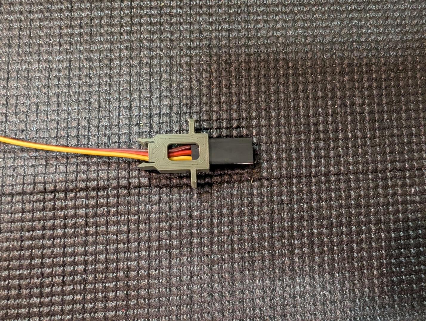
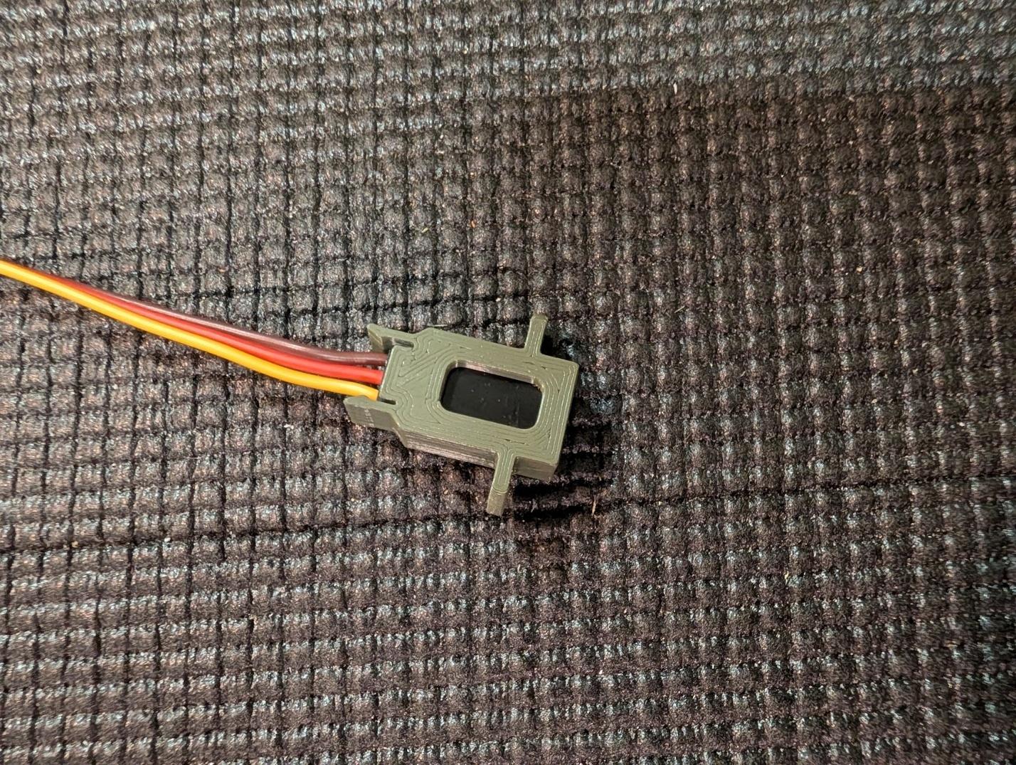
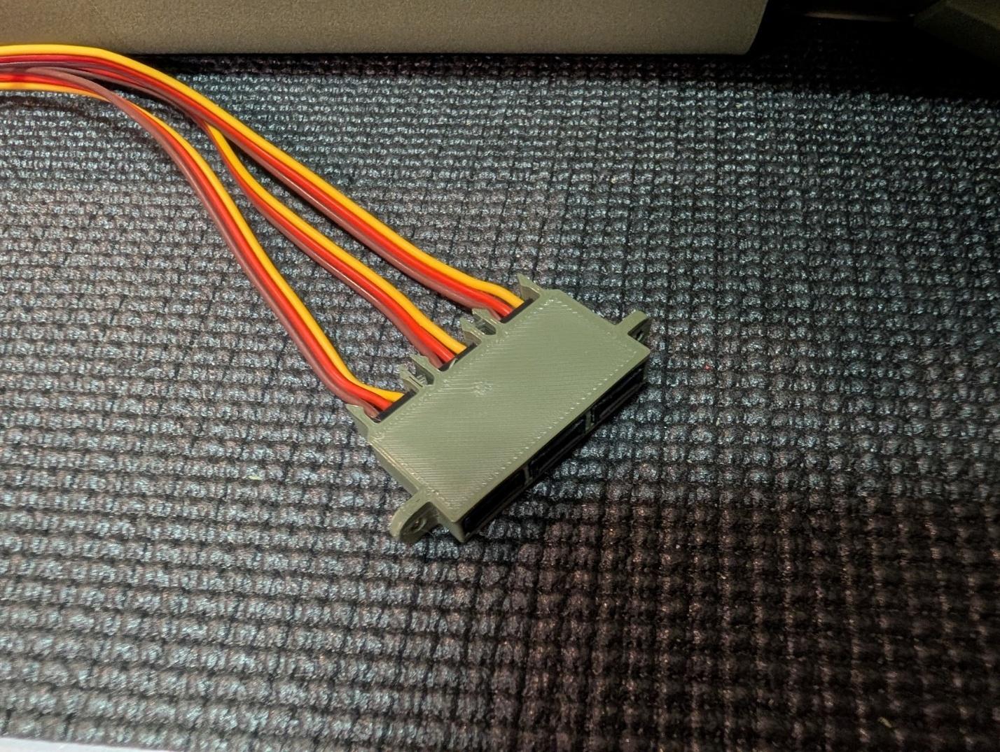
You can mount the female servo connectors to the printed receptacles to rigidly attach them to the roots of the wings and tail. These are optional but help clean up wiring.
-
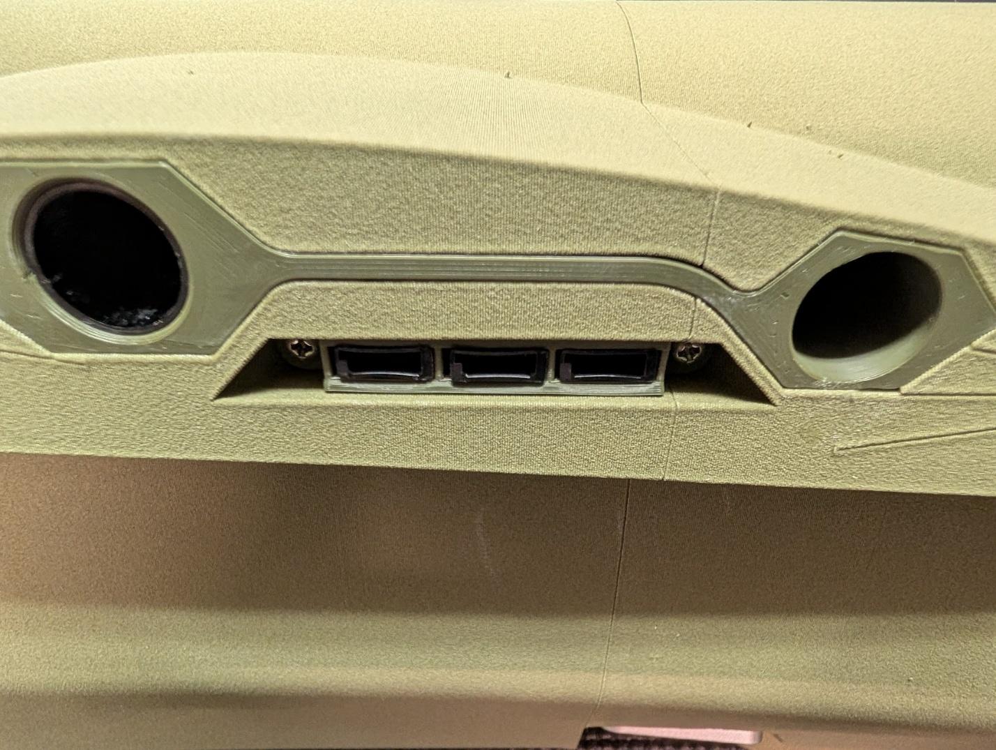
The servo connector receptacles secure to the fuselage with #2 x 3/8" self-tapping screws.
-
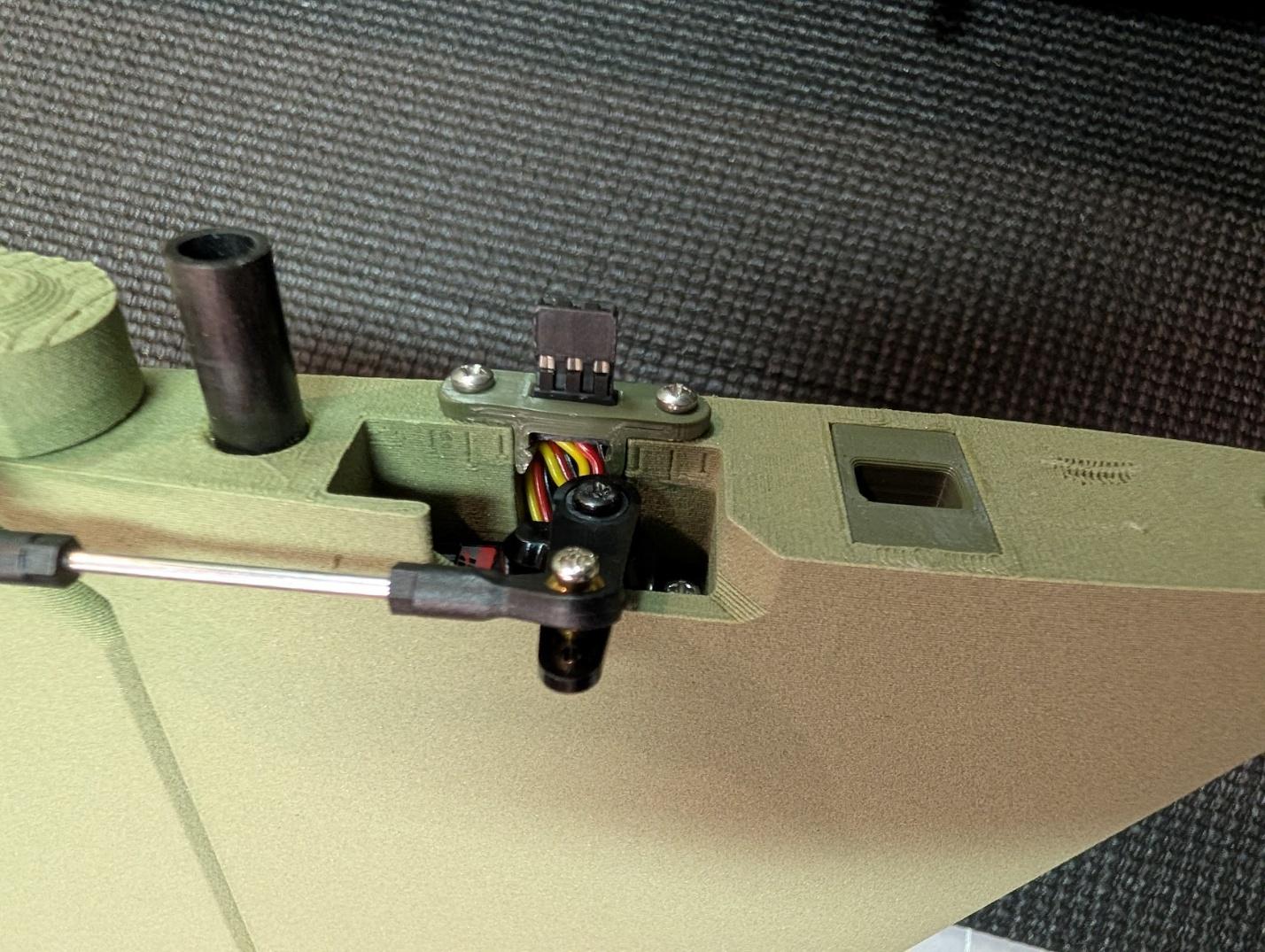
Holders for the male ends of the servo leads are also included. These too are optional – if you choose to use them, you'll need to take extra care to ensure that they are perfectly aligned when installing the wings and tail surfaces.
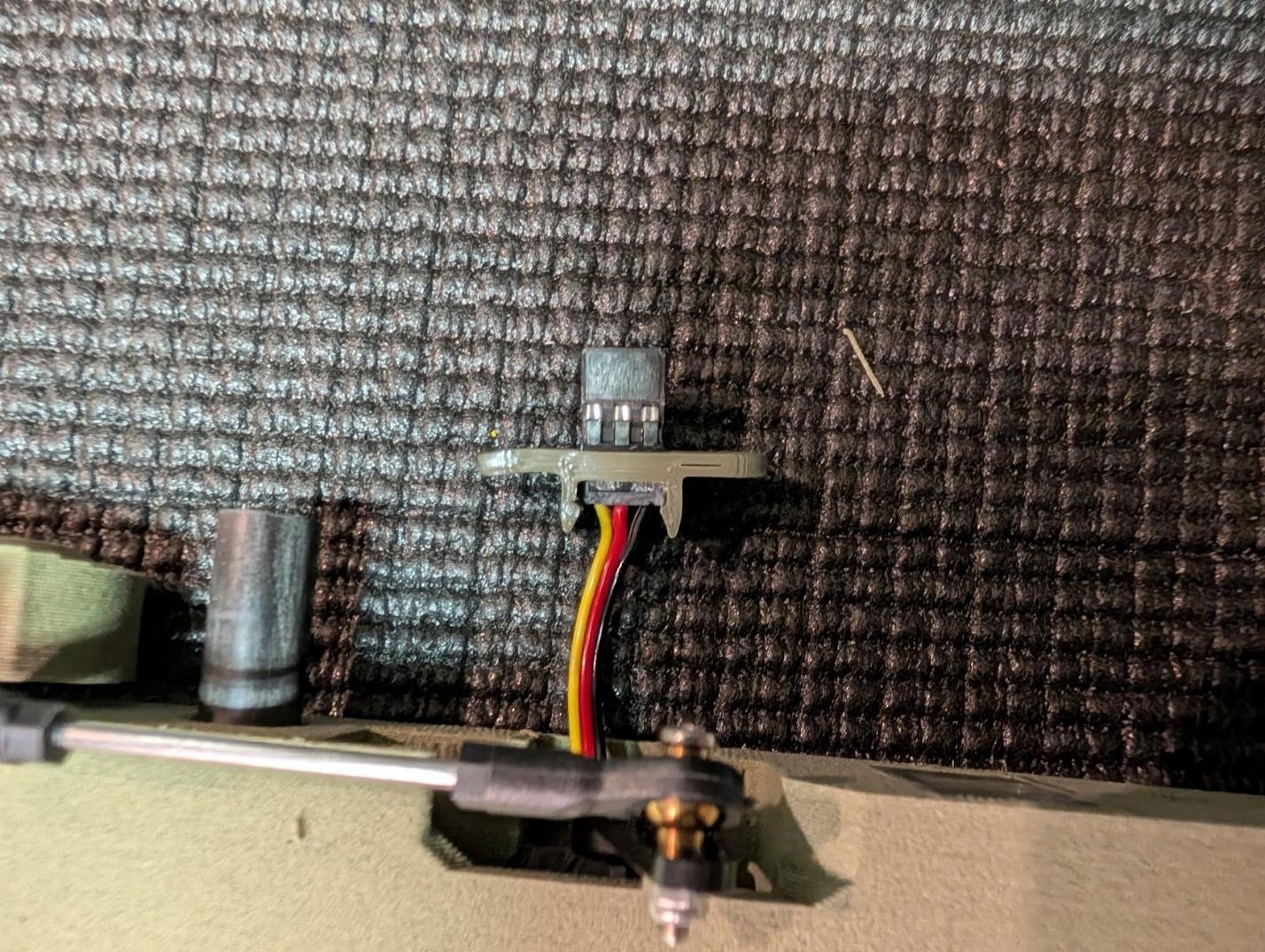
-
Similarly, the male connector holders mount to the roots of the wing and tail surfaces with #2 x 3/8" self-tapping screws.
-
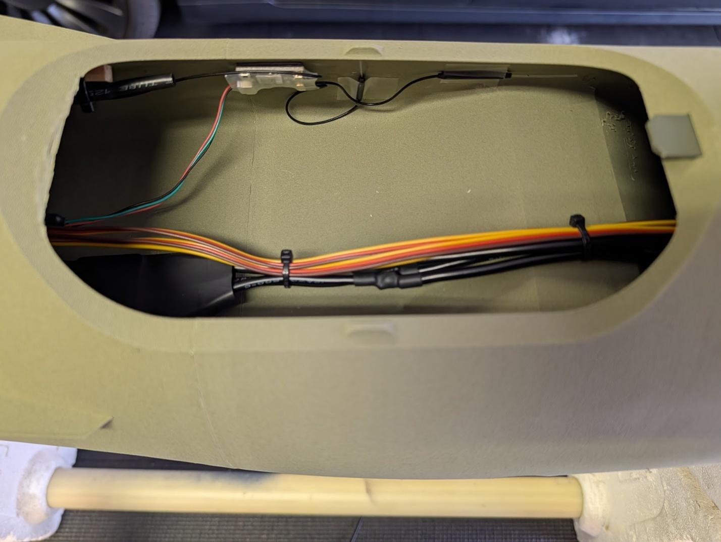
Mount the ESC in the rear avionics hatch area. This is also a good place for your R/C receiver. Secure the wiring as desired.
-
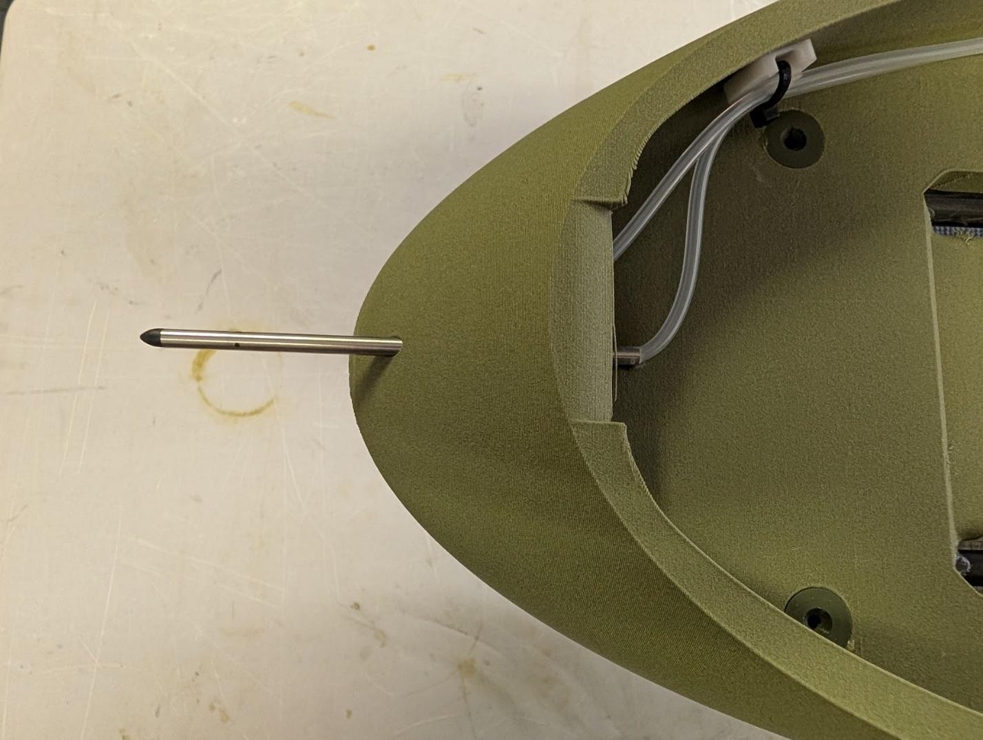
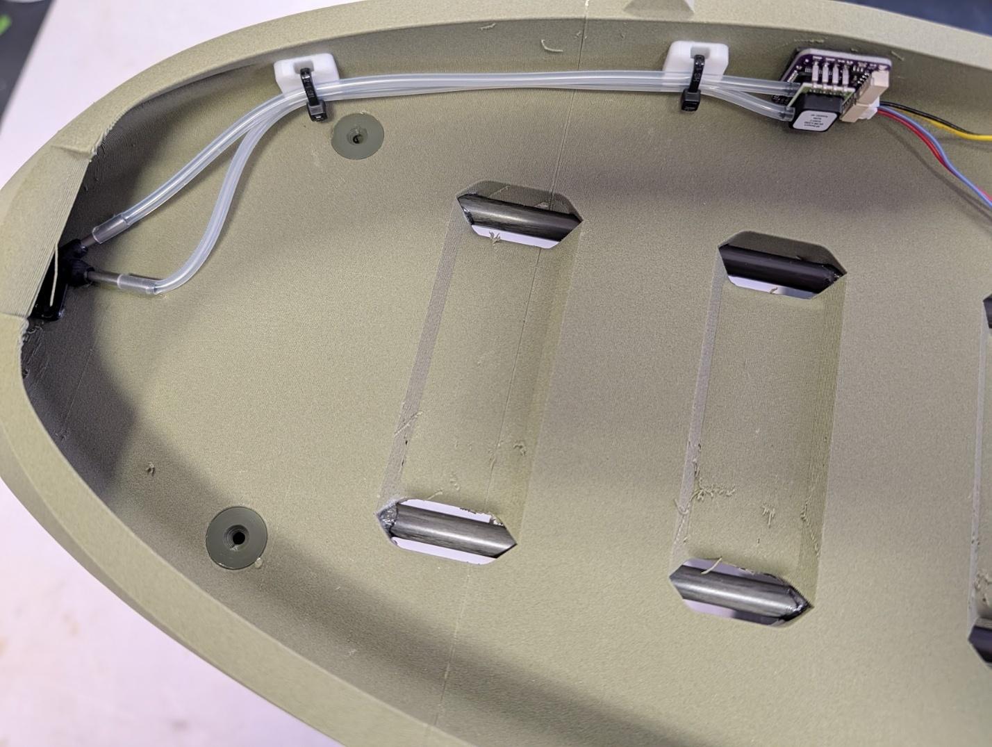
If using an airspeed sensor, mount the pitot tube in the hole at the front of the fuselage and secure with glue.
-
Mount the airspeed sensor in a suitable location and secure the tubes.
-
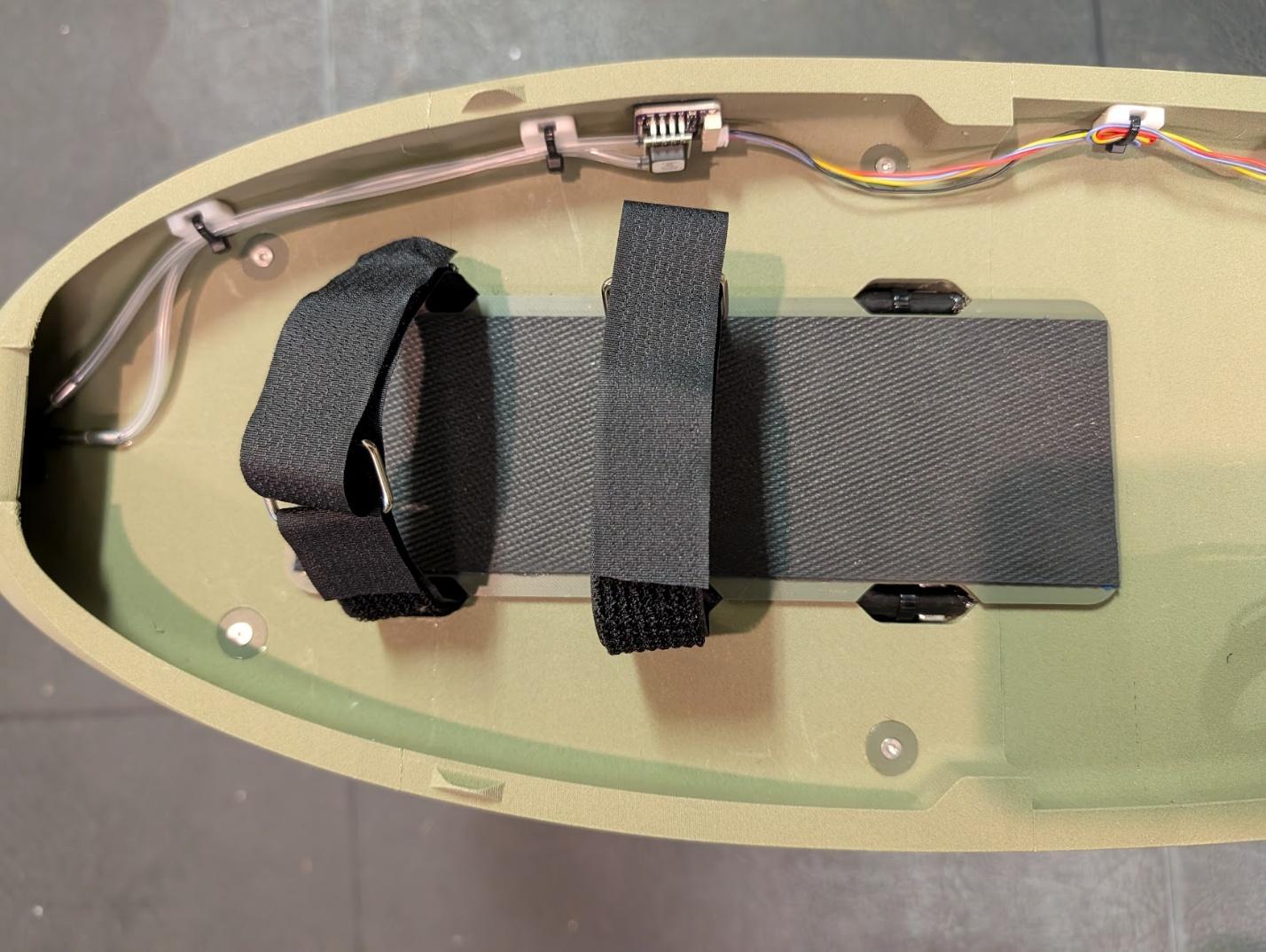
Glue the battery tray to the floor of the forward fuselage, aligning the notches in the sides. Add Velcro, non-slip pads, and straps as desired.
-
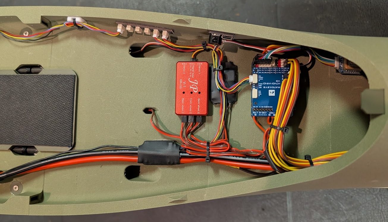
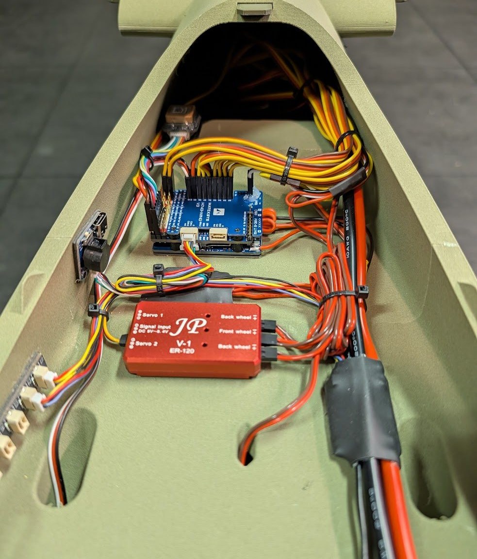
If using a flight controller, arrange it inside the avionics area. Connect the sensors, inputs, and outputs as per the flight controller documentation. If not using a flight controller, wire the servos and sequencer directly to your receiver.
Note
This model has many servos and retracts so be sure to use a BEC capable of powering them all. If you can, using one BEC to power the receiver and servos and another to power the landing gear is preferred. In the prototype, the Matek flight controller's powerful built-in BEC was used to power the servos while the ESC's built-in BEC was wired to power the gear sequencer, retracts, and doors.
-
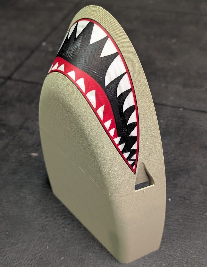
If using the optional nose graphic, now is a good time to glue it to the nose assembly.
-
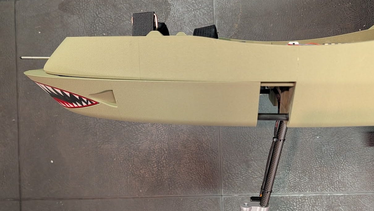
Slide the nose assembly onto the mounting rails and carbon fiber tubes in the underside of the forward fuselage.
-
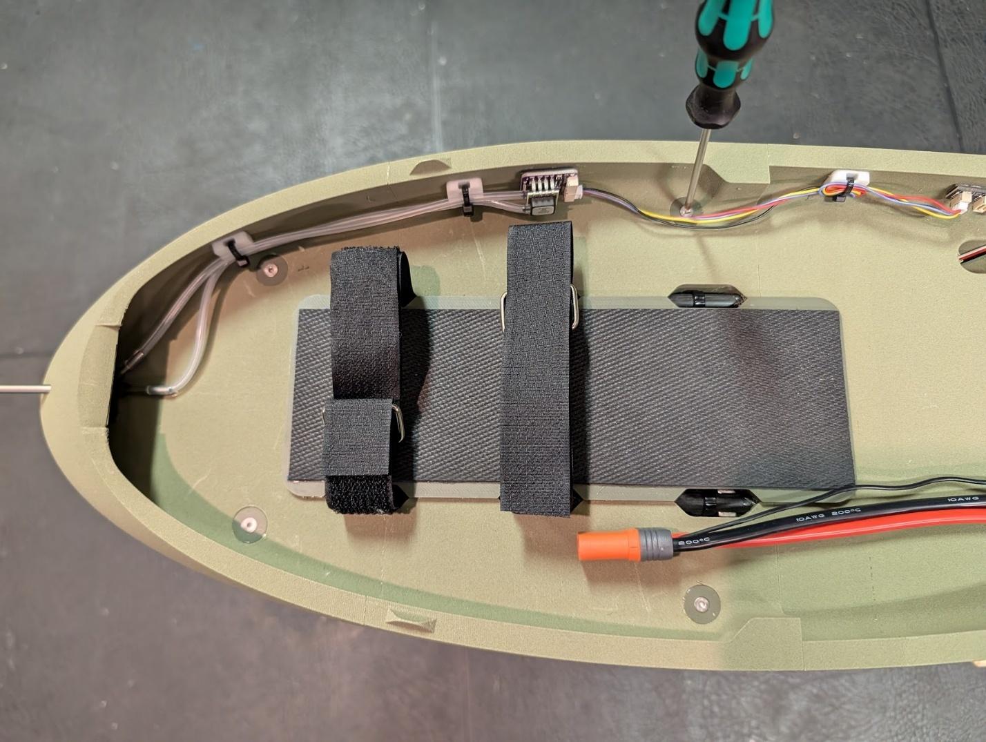
Secure the nose assembly using four M3 x 25mm flat-head screws from the battery area.
-
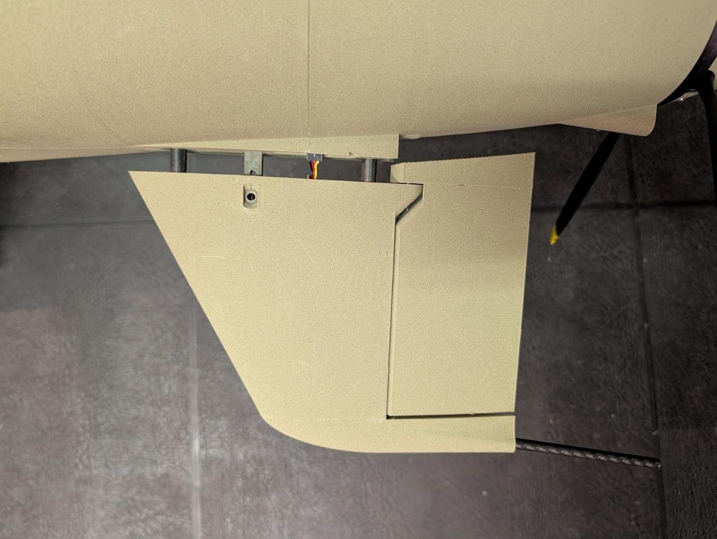
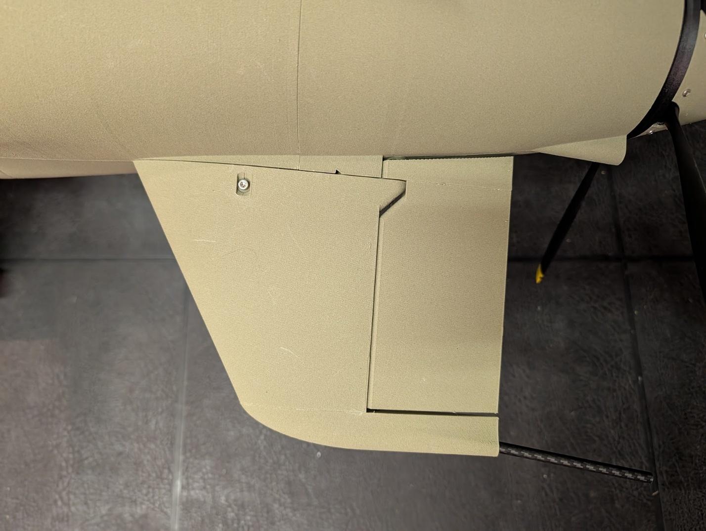
Slide the ventral fin into its receptacles in the fuselage, while connecting the servo lead. Secure with a single M3x20mm cap screw.
-
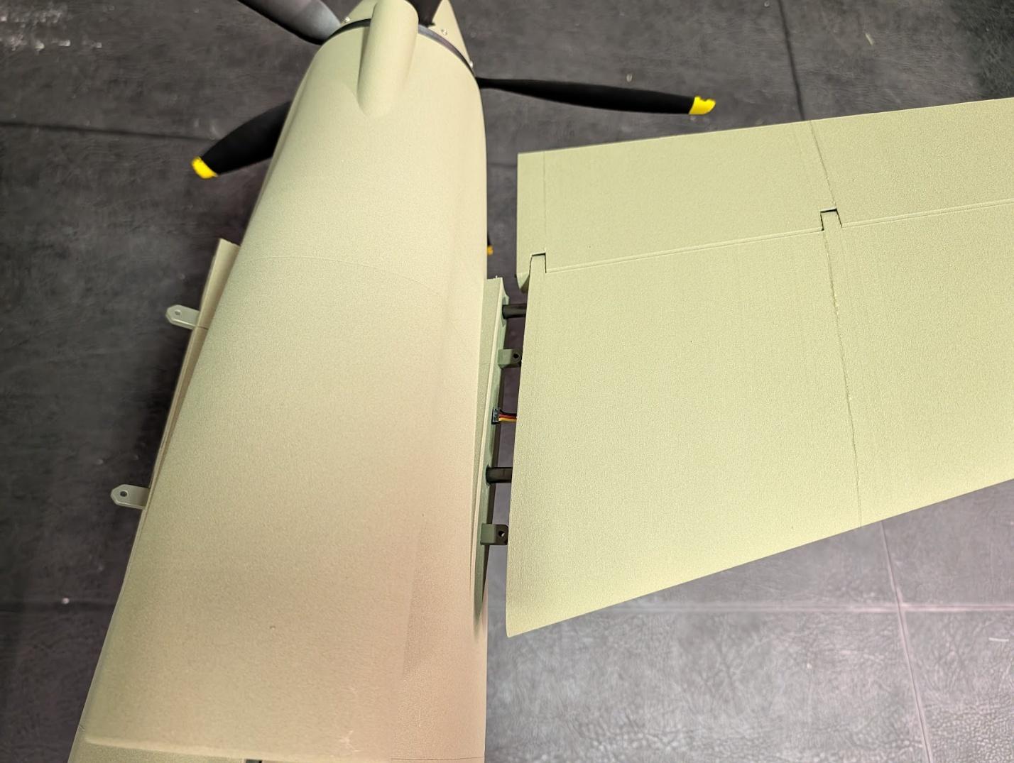
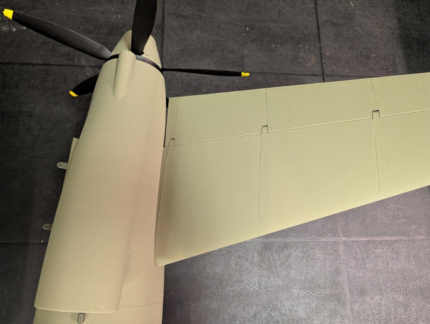
Slide the stabilizers into their receptacle tubes in the fuselage, while connecting the servo leads.
-
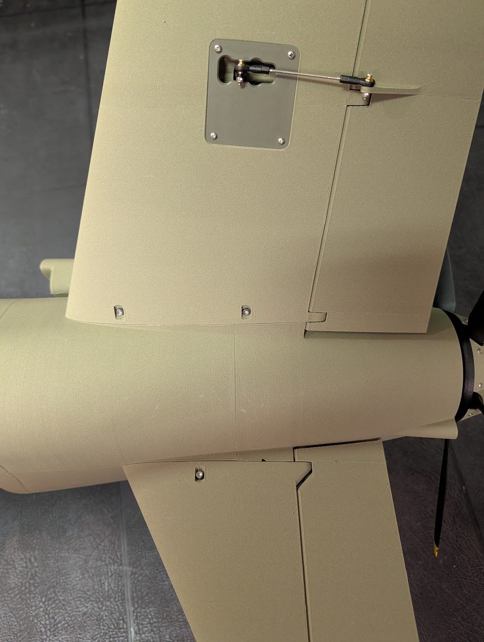
Secure with two M3x20mm cap screws each.
-
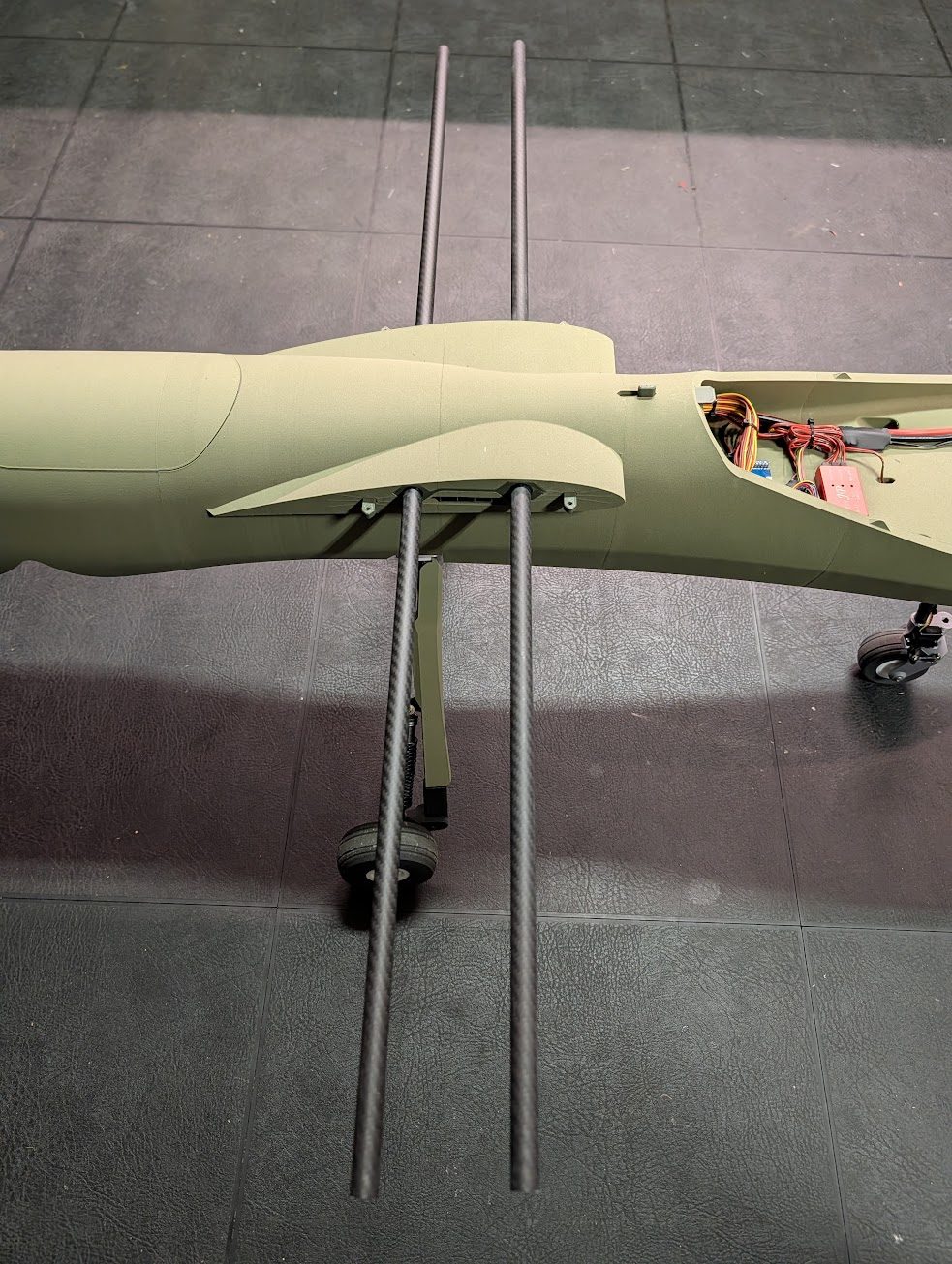
Prepare the two 14mm diameter, 1m long carbon fiber wing tubes and insert them into the fuselage.
-
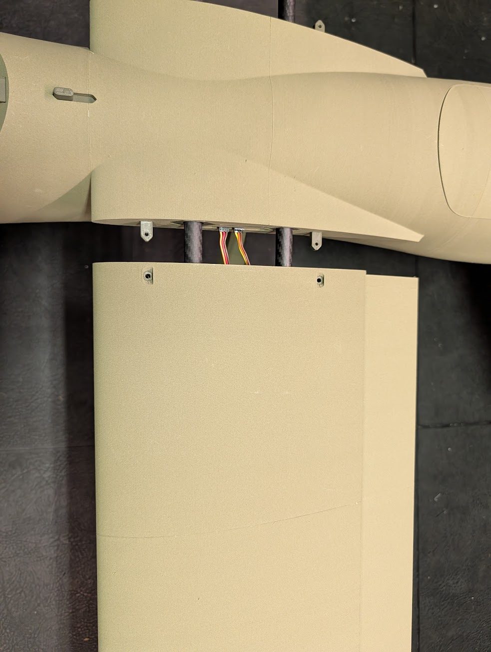
Slide the wing panels onto the spar tube.
-
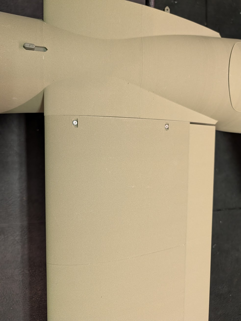
Fasten the wing panels using two M3x20mm cap screws each.
Pre-flight setup
Adjust control deflections using the suggested throws below. Dual rates are optional depending on your preferences. Though regardless, consider using 20% - 40% expo for a smooth control response.
Suggested control throws
| Control | Travel | Measured at |
|---|---|---|
| Aileron | 35 mm up / 25 mm down | Root |
| Elevator | 25 mm up / 15 mm down | Tip |
| Rudder | 40 mm left / 40 mm right | Tip |
| Flaps | 40 mm at full deflection | Root |
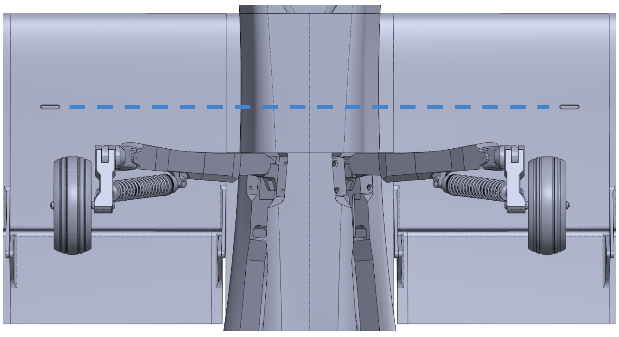
The recommended CG is marked with indentations in the underside of the wings. Ensure that the model balances at this location with the battery, electronics, and all hatches installed. The landing gear should be extended during balancing.
Congratulations – you're ready to fly!
Optional Micro Cruiser pylons
The Mojave download contains wing pylons compatible with the Micro Cruiser design found HERE. It's a great design that's a lot of fun to drop from the Mojave and also to fly standalone.
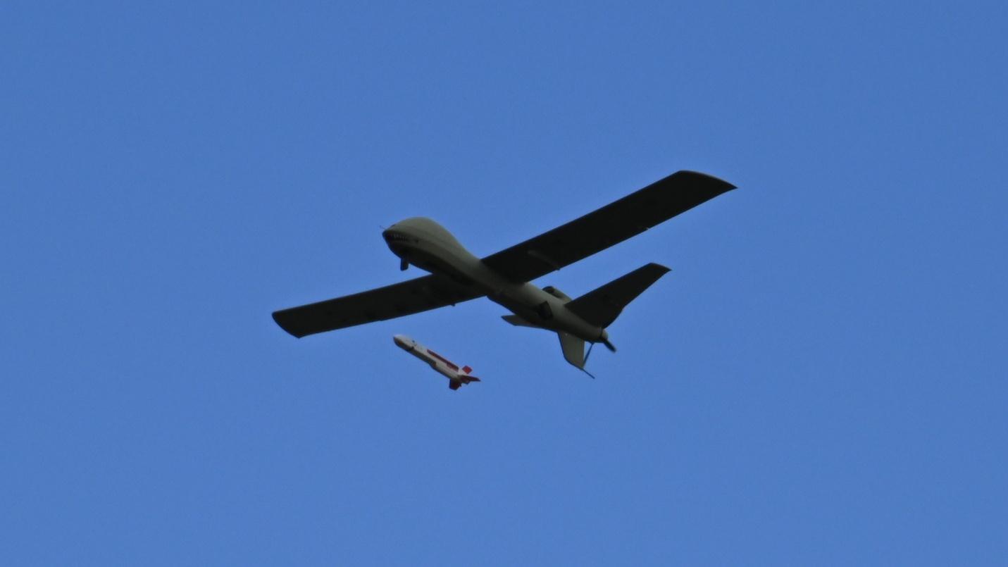
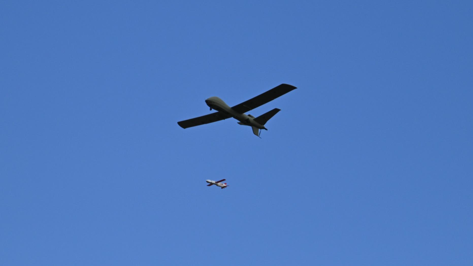
The pylons use the linkage parts from the Micro Cruiser download, actuated by a 5.6g metal gear servo. They secure to the wings with three #4x7/8" self-tapping screws per side.
Contact us
Have a question, issue, or just a cool idea for the next aircraft we should model? Drop us an email at: info@loftedaero.com