F-35B VTOL for 70mm EDF — Build Guide
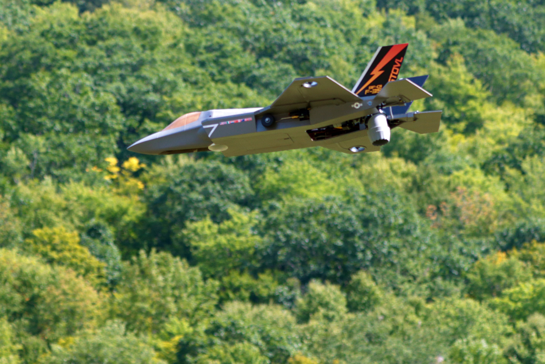
At a glance
- Difficulty: Advanced to build and fly
- Wingspan: 778 mm (30.6")
- Length: 1139 mm (44.8")
- Flying weight: 2700 g (6.0 lb)
Overview
Thank you for purchasing a model by Lofted Aero! 3D printed aircraft are an exciting new segment of the hobby, and we've got no shortage of ideas for new designs. Your support helps us make those reality.
The F-35B represents the pinnacle of aviation technology – a supersonic fighter jet capable of vertical takeoff and landing (VTOL) while maintaining a low radar cross section. While this model won't break the sound barrier, it does replicate the F-35B's VTOL capability with impressive stability. This feature was unheard of in EDF jet models until recently, and is sure to wow everybody at the flying field.
This model is designed to be equipped with an autopilot running Ardupilot software for the stability and control necessary for fully functional VTOL flight. In addition, the Lofted Aero 3BSM and its electronics package are required for completion.
Skill meter
Build: This model is straightforward to build, with simple foam and 3D printed parts. However, advanced components such as the 3BSM, flight controller, and Ardupilot software add complexity.
Flight: This model has smooth handling characteristics but is fast and has a moderate wing loading. It is intended for pilots with prior EDF jet experience.
Specifications
| Spec | Value |
|---|---|
| Wingspan | 778mm (30.6") |
| Length | 1139mm (44.8") |
| Wing Area | 22.6dm2 (2.43ft2) |
| Airframe Weight | 800g (1.8lb) |
| Flying Weight | 2700g (6.0lb) |
| Wing Loading | 119g/dm2 (39.2oz/ft2) |
| Airfoil | KFm2 Step |
Recommended equipment
The following hardware & electronics are required to complete the F-35B. In addition, you'll need some adhesives, your R/C transmitter and receiver, and a LiPo battery charger.
Construction materials
| Item | Details |
|---|---|
| Foam Board (3x 20" x 30" sheets) | Flite Test Foam Board or Water-Resistant Foam Board or Dollar Tree Foam Board |
| Wing and Fuselage Spars | 10mm x 1000mm Carbon Square Tubes (1 pack) |
| Spar Joiners | 8mm x 330mm Carbon Tubes (1 pack) |
| Nose Joiners | 5/16" (8mm) Square Wood Dowel |
| Strapping Tape | Extreme Shipping Tape |
Filament
Good filament matters more here than on most prints. The materials below have been tested with our filament and process settings and produce good results. Alternate options are listed as well, though weight and durability may vary.
| Use | Filament | Amount |
|---|---|---|
| LW-PLAAirframe skins — wings, tail and fuselage. | 3DLabPrint PolyLight or ColorFabb LW-PLA or Bambu PLA Aero | ~217 g |
| PLAStructure, accessories, and thin-wall airframes. | 3DLabPrint PolyAir or eSun PLA+ or Bambu PLA Tough+ | ~219 g |
| Alternate material options | ||
| LW-ASA replaces LW-PLAHeat and UV resistant. Needs a heated enclosure and the 0.20mm LW-ASA profiles — see Profiles used by this model. | ColorFabb LW-ASA or Bambu ASA Aero | — |
| PETG replaces PLAHigher heat tolerance. Same process profile — load your slicer's own PETG filament preset. | Bambu PETG Basic or Hatchbox PETG | — |
Power system & avionics
| Item | Details |
|---|---|
| Motor, EDFs, and ESCs | FMS 70mm EDF Power Combo for 6S (x2) |
| Roll Thruster Motors | T-Motor F1404 3800kV (x2) |
| Roll Thruster ESCs | Flycolor 35A (x2) |
| Roll Thruster Connectors | MR30 |
| Roll Thruster Props | Gemfan D51 |
| Battery | Admiral Pro 6S 4000mAh 60C |
| Battery Connector | EC5 |
| Flight Control and Nose Steering Servos | Hitec HS-5070MH (x3) |
| Retract Set | 40G Electric Retract System |
| Medium Servo Extensions | 30cm Servo Extension |
| Long Servo Extensions | 60cm Servo Extension |
| Main Motor & Battery Leads | 10AWG Silicone Wire |
| Flight Controller Power Leads | 16AWG Silicone Wire |
| Roll Motor Leads | 22AWG Silicone Wire |
Note: Various common hobby components – such as wires, connectors, and glue – may also be required.
Autopilot equipment — Option 1: Matek
| Item | Details |
|---|---|
| Flight Controller | Matek H743-Wing v3 |
| GPS Receiver | Matek M10Q GNSS |
| Telemetry Radio (Optional) | 3DR Telemetry Radio Set |
Autopilot equipment — Option 2: Team Black Sheep
This autopilot configuration is comparable to the Matek, but may be easier to source in some markets.
| Item | Details |
|---|---|
| Flight Controller | TBS Lucid H7 Wing |
| GPS Receiver | TBS M10Q GNSS |
| Telemetry Radio (Optional) | 3DR Telemetry Radio Set |
3BSM equipment
3BSM print files are included with this model. Please refer to 3BSM build guide videos for additional details.
| Item | Details |
|---|---|
| Electronics | 3BSM Electronics Pack - Select MD70MH Servos |
Hardware
| Item | Part |
|---|---|
| Hinge Rods & Pushrods | 1.2mm Pushrods |
| Landing Gear Struts | 3mm Steel Rod |
| Landing Gear Couplers | 3mm to 4mm Coupler |
| Landing Gear Stoppers | 0.12" Collars |
| Main Wheels | 2" Super Lite Wheels |
| Nose Wheel | 1-3/4" Super Lite Wheel |
| M3 Threaded Inserts | M3 Short Insert (x28, pack contains 100) |
| Wing and Lower Nose Mount Screws | M3 x 20mm Cap Screws (x6) |
| 3BSM and Fan Mount Screws | M3 x 10mm Cap Screws (x6) |
| Wing and Fan Mount Washers | M3 Flat Washers (x10) |
| Retract Mount Screws | M3 x 6mm Countersunk Screws (x12) |
| Vertical Tail Mount Screws | M3 x 16mm Cap Screws (x4) |
| Upper Nose and Servo Mount Screws | #2 x 5/16" Self-Tapping Screws (x8) |
| Servo Mount Washers | #2 Flat Washers (x6) |
Note: A convenient hardware pack containing all inserts and fasteners is available from Lofted Aero HERE.
Printing thin-wall models
Desktop 3D printers are perfectly capable of producing great-flying R/C models durable enough to withstand hangar rash and general use. However, aircraft designs contain a unique mix of thin surfaces and intricate solid supports that require some practice to print perfectly. Keep the following tips in mind when printing your model.
Slicing the project files
The model download includes .3MF project files for both Bambu Studio and OrcaSlicer – modern, free, and open source slicers with wide support for popular printers and the ability to utilize multiple plates and varying settings within a single project. These project files include print settings tailored to the model as well as filament settings with adjusted temperature and retractions. The provided settings have been tested to suit a wide range of printers – in most cases, no changes should be necessary aside from choosing your printer.
Open the folder for the slicer you're running. The two sets are equivalent and the workflow is the same in both, but each is written in its own slicer's settings dialect, so they aren't interchangeable.
The process and filament presets these projects use are our own. You don't need them to print – the project files already carry the settings – but importing them once from the Print Settings page keeps them in your slicer for future projects, and that page explains what each one is for.
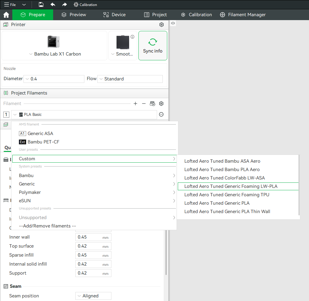
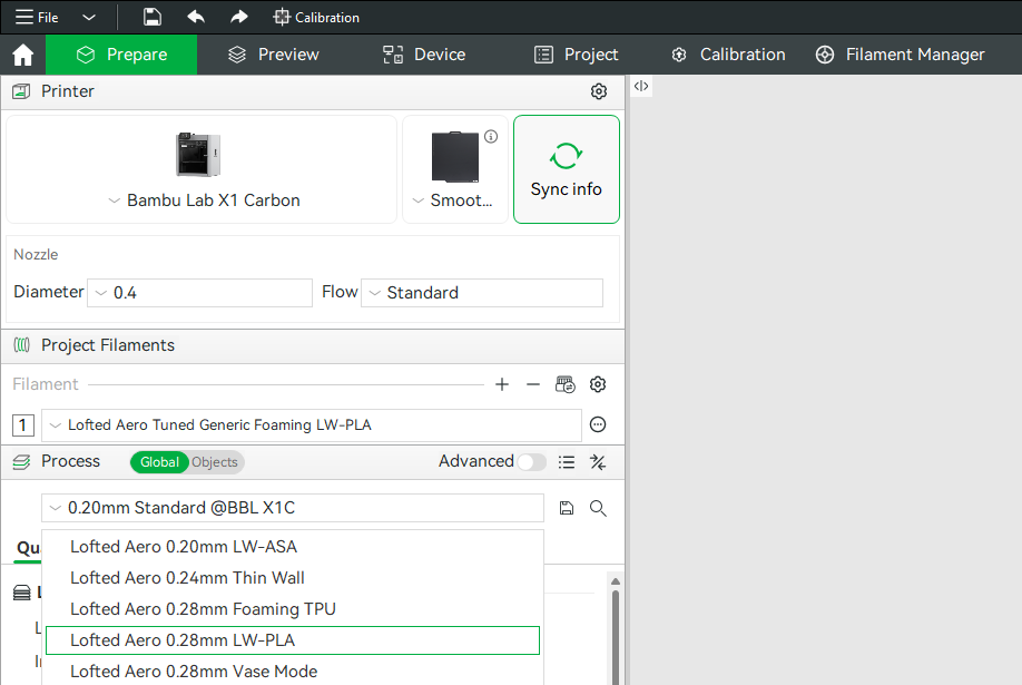
Generic example screenshots
These happen to show the LW-PLA profiles being picked. The profiles this model uses are listed just below.
Profiles used by this model
| Project file | Process profile | Filament profile |
|---|---|---|
| LW-PLA Parts | Lofted Aero 0.28mm LW-PLABambu Studio OrcaSlicer | Lofted Aero Tuned Generic Foaming LW-PLABambu Studio OrcaSlicer |
| LW-PLA Vase Mode Parts | Lofted Aero 0.28mm Vase ModeBambu Studio OrcaSlicer | Lofted Aero Tuned Generic Foaming LW-PLABambu Studio OrcaSlicer |
| PLA Parts | Your slicer's own 0.20mm Standard |
Lofted Aero Tuned Generic PLABambu Studio OrcaSlicer |
Hardware parts like latches, trays, mounts and gear ride your slicer's own stock profile, which is already matched to your printer.
Printing the airframe in LW-ASA instead? Substitute Lofted Aero 0.20mm LW-ASA for the LW-PLA process profile, with either the Bambu ASA Aero or ColorFabb LW-ASA filament profile from the Print Settings page. LW-ASA needs a heated enclosure. Everything else in the table is unchanged.
Modifiers and per-object settings
Both slicers allow per-object modifications to slicing settings, and this method is used heavily in the provided .3MF files. Where a part needs extra perimeters, different infill, or a relocated seam, that's applied as a per-object modifier on top of the profile rather than as a separate profile. When making settings changes, be mindful of these per-object settings as well as any other modifiers applied to each part. Switch the Process panel from Global to Objects to see every part in the project, the settings overridden on it, and any modifier volumes attached to it.
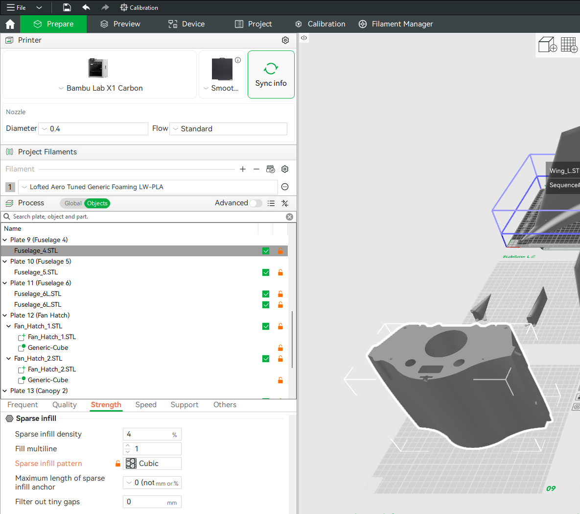
(example screenshot shown – may not represent this model)
Mirrored parts
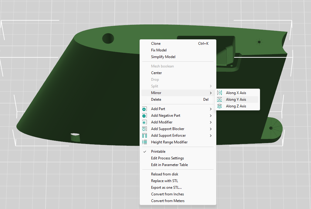
You'll notice that the included STL files often contain parts for only one side of symmetrical components like wings, tail surfaces, and landing gear. Don't worry – you can simply mirror these parts in your slicer to produce the other side. When using the included .3MF project files, this mirroring has already been done.
Other printing options
If you'd rather configure and slice the STL files yourself with the software and method of your choice, refer to the print table below for the profile and modifiers applied to each part.
A few things to keep in mind:
- Retraction should be just enough to prevent stringing between features
- Extra length on restart should be just enough to prevent sparse extrusion at layer start
- Extrusion ratio should be adjusted until print weight equals the suggested part weight
Print table
Reference print profiles, per-part modifiers, and weights for each part.
| Part | Weight | Print Profile | Modifiers |
|---|---|---|---|
| LW-PLA | |||
| Nose 1 | 14g | Lofted Aero 0.28mm Vase Mode0.28mm Height 0.42mm Extrusion Width 1 Perimeter 0 Top / 0 Bottom Layers Cross Hatch @ 0% Nearest Seam Classic Wall Generator 238°C Nozzle / 56°C Bed |
— |
| Nose 2 | 20g | ||
| Nose 3 | 26g | ||
| Fuselage 1 | 24g | ||
| Fuselage 2 | 17g | ||
| Hatch 1 | 12g | ||
| Hatch 2 | 3g | ||
| Fan Covers | 2g total | Lofted Aero 0.28mm LW-PLA0.28mm Height 0.42mm Extrusion Width 1 Perimeter 3 Top / 3 Bottom Layers 2D Lattice @ 4% Back Seam Classic Wall Generator 238°C Nozzle / 56°C BedModifiers on every part in this group:Gyroid Infill Nearest Seam |
|
| Lift Fan Duct | 11g |
| |
| Tail Support (L & R) | 5g each |
| |
| Stabilator Stiffener (L & R) | 3g each |
| |
| Vertical Tail Base (L & R) | 10g each |
| |
| Cooling Vents | 4g total |
| |
| 3BSM Section 1 | 13g |
| |
| 3BSM Section 2 | 9g | ||
| 3BSM Section 3 | 9g | ||
| 3BSM Section 4 | 8g | ||
| 3BSM Nozzle | 9g |
| |
| Total LW-PLA | 217g | ||
| PLA | |||
| Fan Mounts (Aft 3BSM Brace, Aft & Forward 3BSM Mount, Lift Fan Mount L & R) | 39g total | Your slicer's own 0.20mm Standard0.20mm Height 0.42mm Extrusion Width 2 Perimeters 5 Top / 3 Bottom Layers 15% Infill (Grid in Bambu Studio, Cross Hatch in OrcaSlicer) Aligned Seam Classic Wall Generator 210°C Nozzle / 60°C Bed |
|
| Battery Holder (x2) | 25g total |
| |
| Landing Gear Mounts (Main Gear Mount Lower & Upper L & R, Nose Gear Mount) | 56g total |
| |
| Accessories (Bottom & Top Hatch Latch parts, Control Horn L & R, Stabilator Hinge Inserts 6x, Servo Mount Plate 2x, Strut Bend Guide) | 36g total |
| |
| Roll Thruster (2x) | 9g each |
| |
| 3BSM Servo Mounts | 6g total |
| |
| 3BSM Ring Gears | 26g total |
| |
| 3BSM Ring Inserts | 11g total |
| |
| 3BSM Pinion Gears | 2g total |
| |
| Total PLA | 219g | ||
Preparation
-
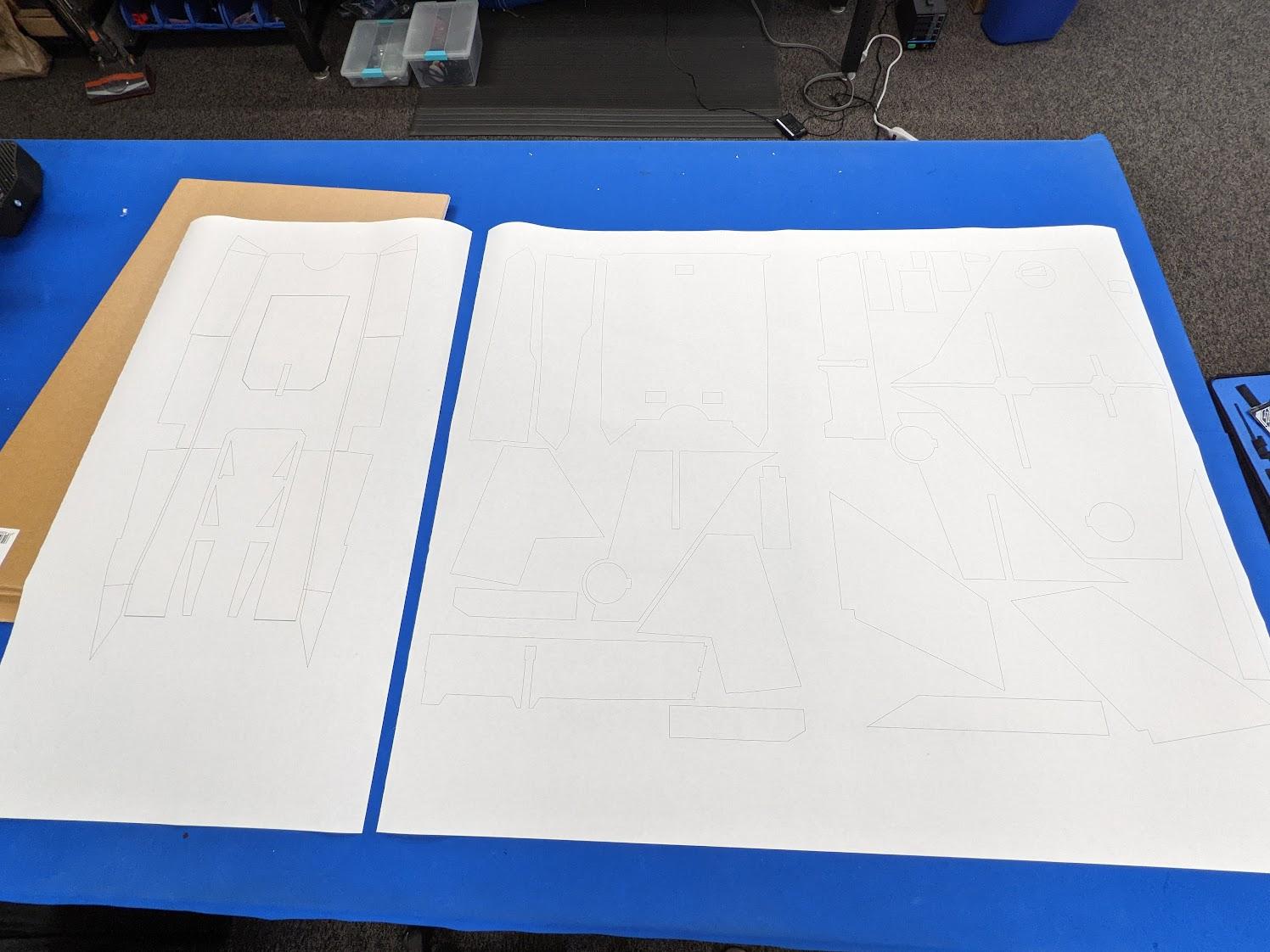
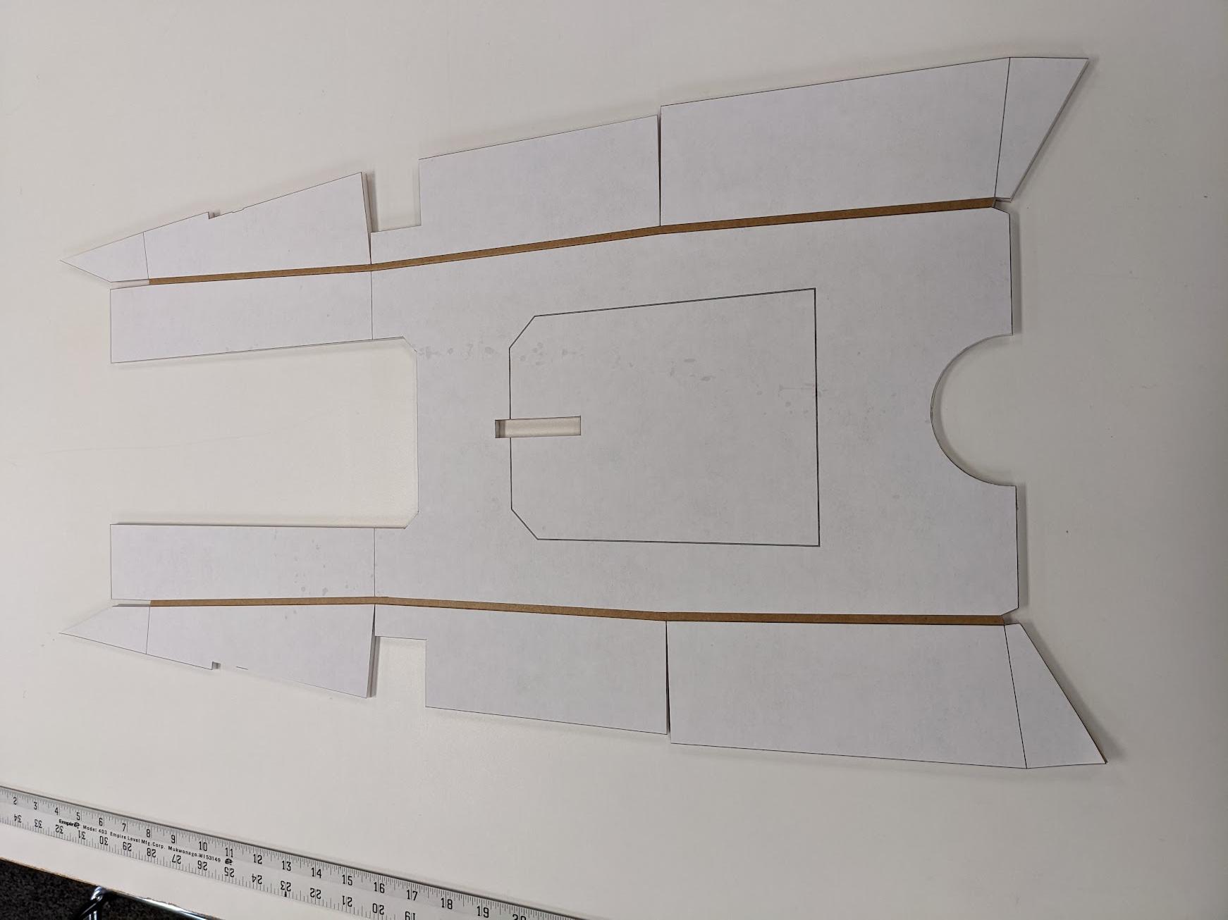
Print the templates on large-format plotter paper. Adhere them to foam board with a light dusting of spray adhesive. They should fit on three 20" x 30" sheets.
-
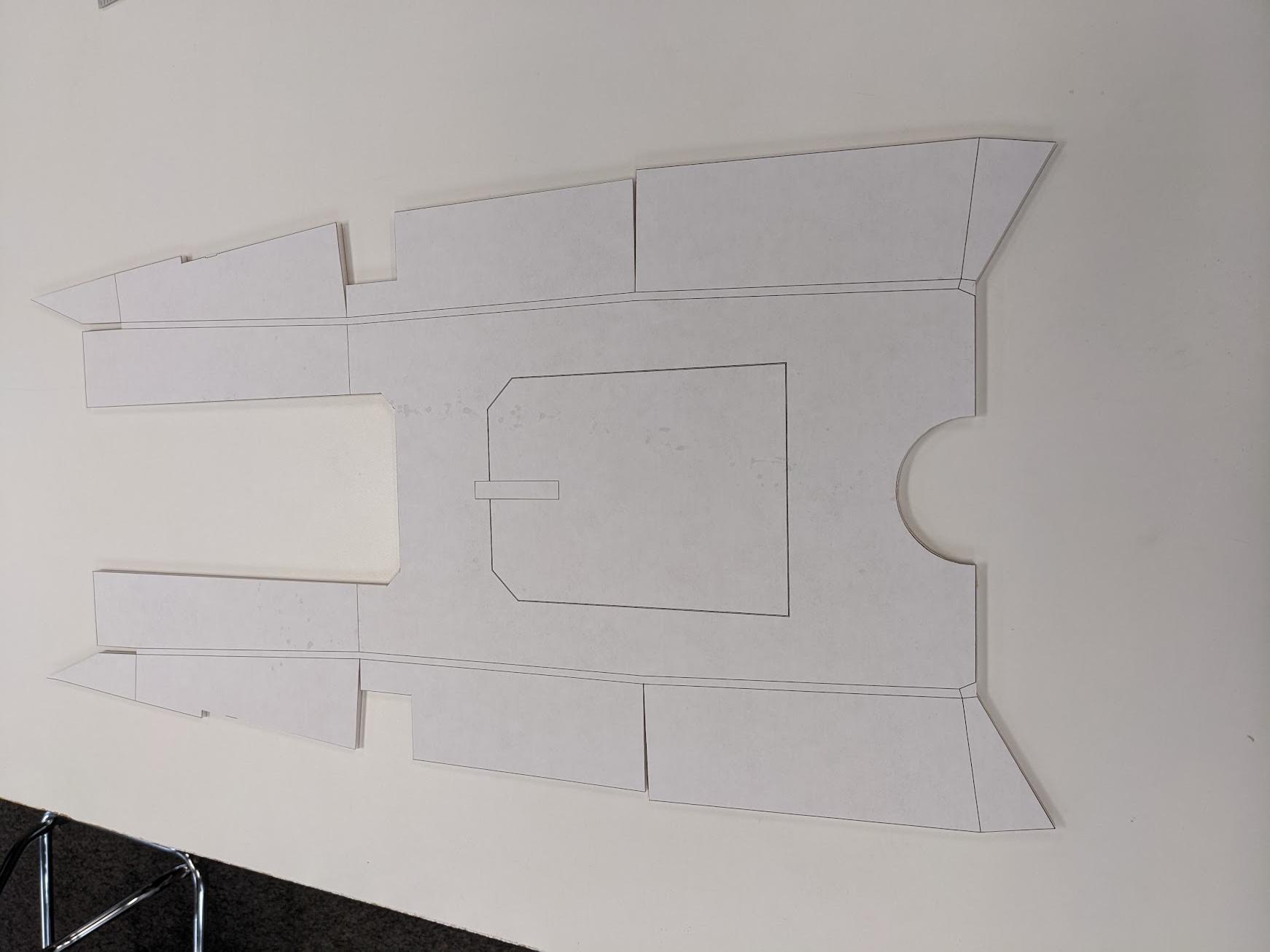
Cut out the lower fuselage shell. For the double sets of lines between the bottom face and side panels of the part, only cut about halfway through the foam.
-
Remove the paper template from those areas.
-
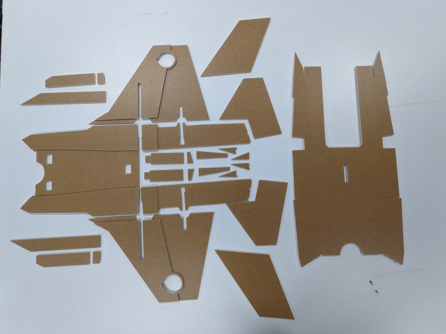
Cut out all remaining foam parts.
Wing assembly
-
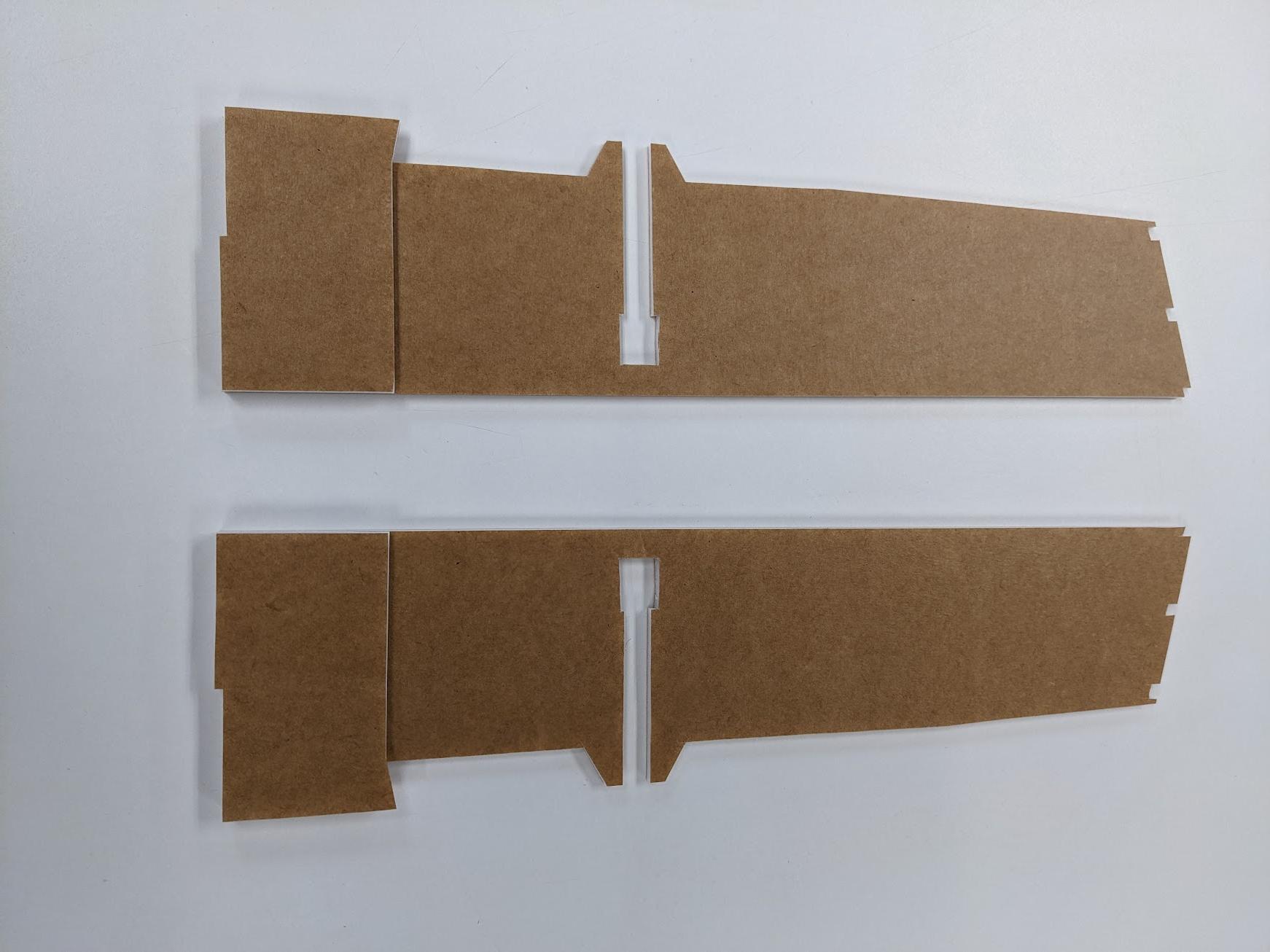
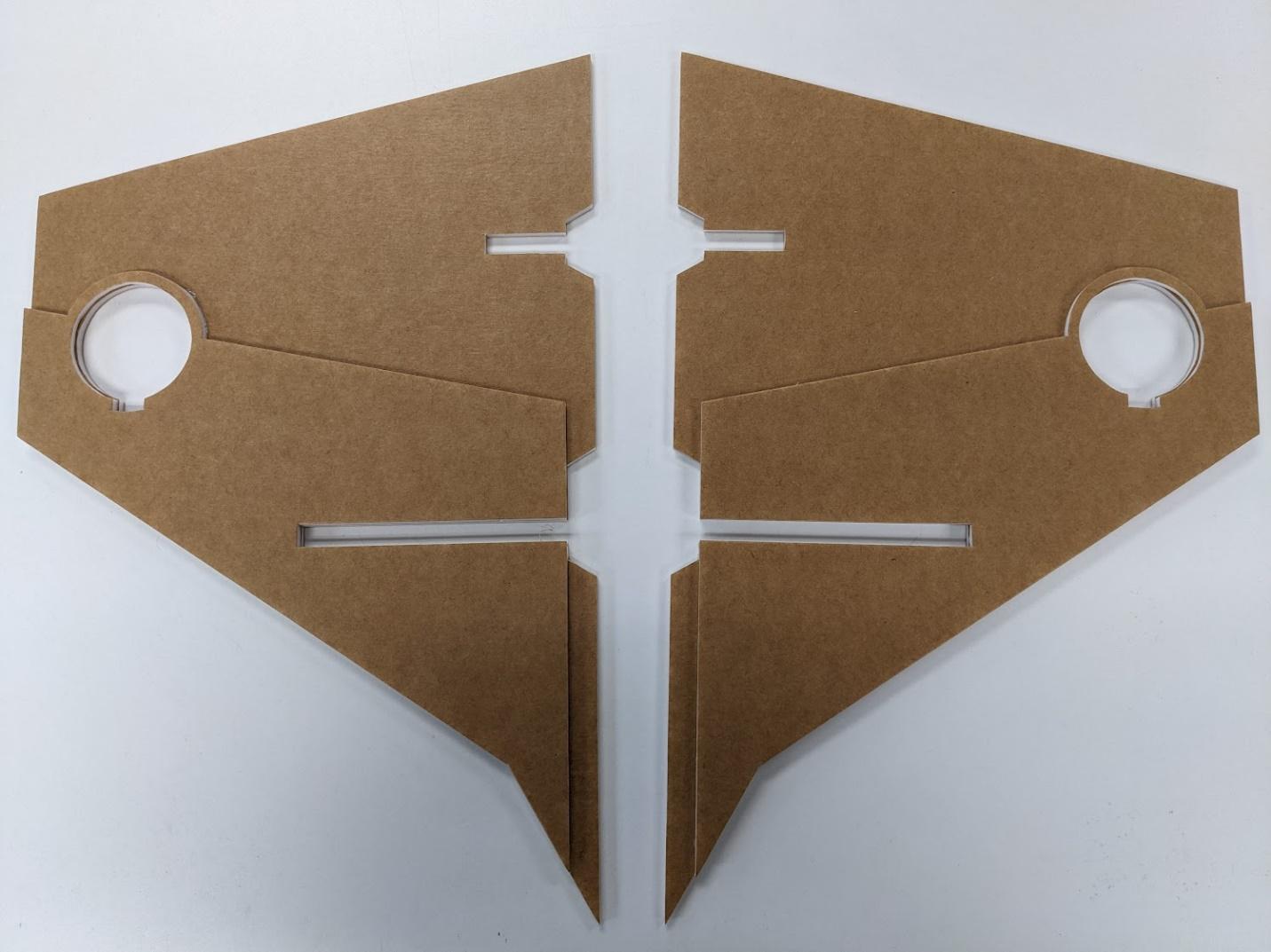
Using UHU-Por, Foam-Tac, or epoxy, laminate the parts shown.
-
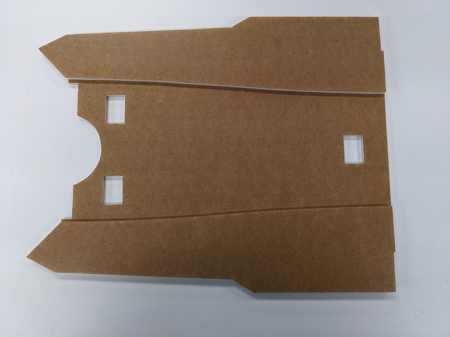
Similarly, laminate the side doublers of the forward wing section.
-
Laminate the upper doublers onto each wing panel.
-
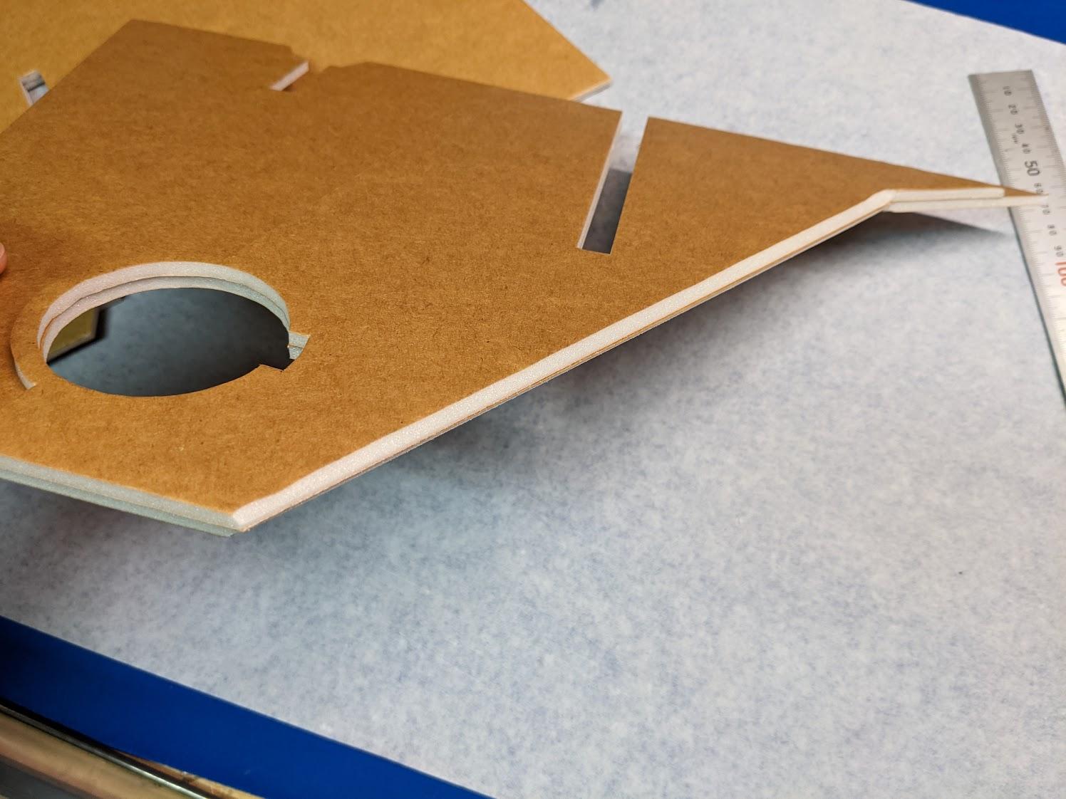
Bevel the leading edges of the wing on both the top and bottom.
-
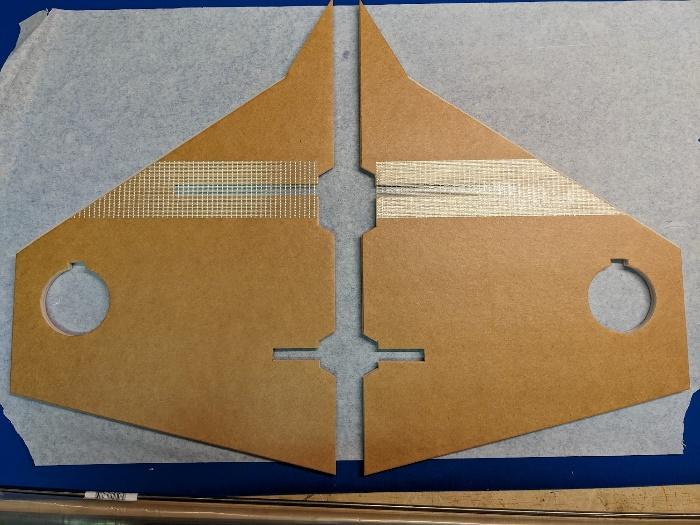
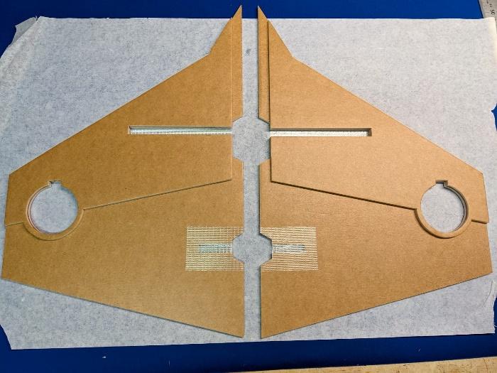
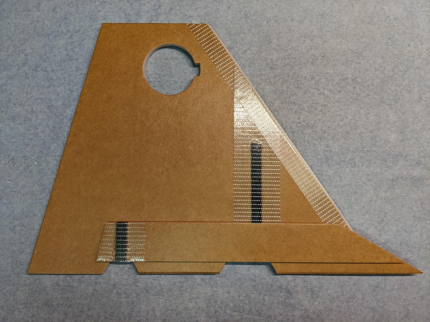
Apply strapping tape to the bottom front and top aft spar areas of the wing panels as shown.
-
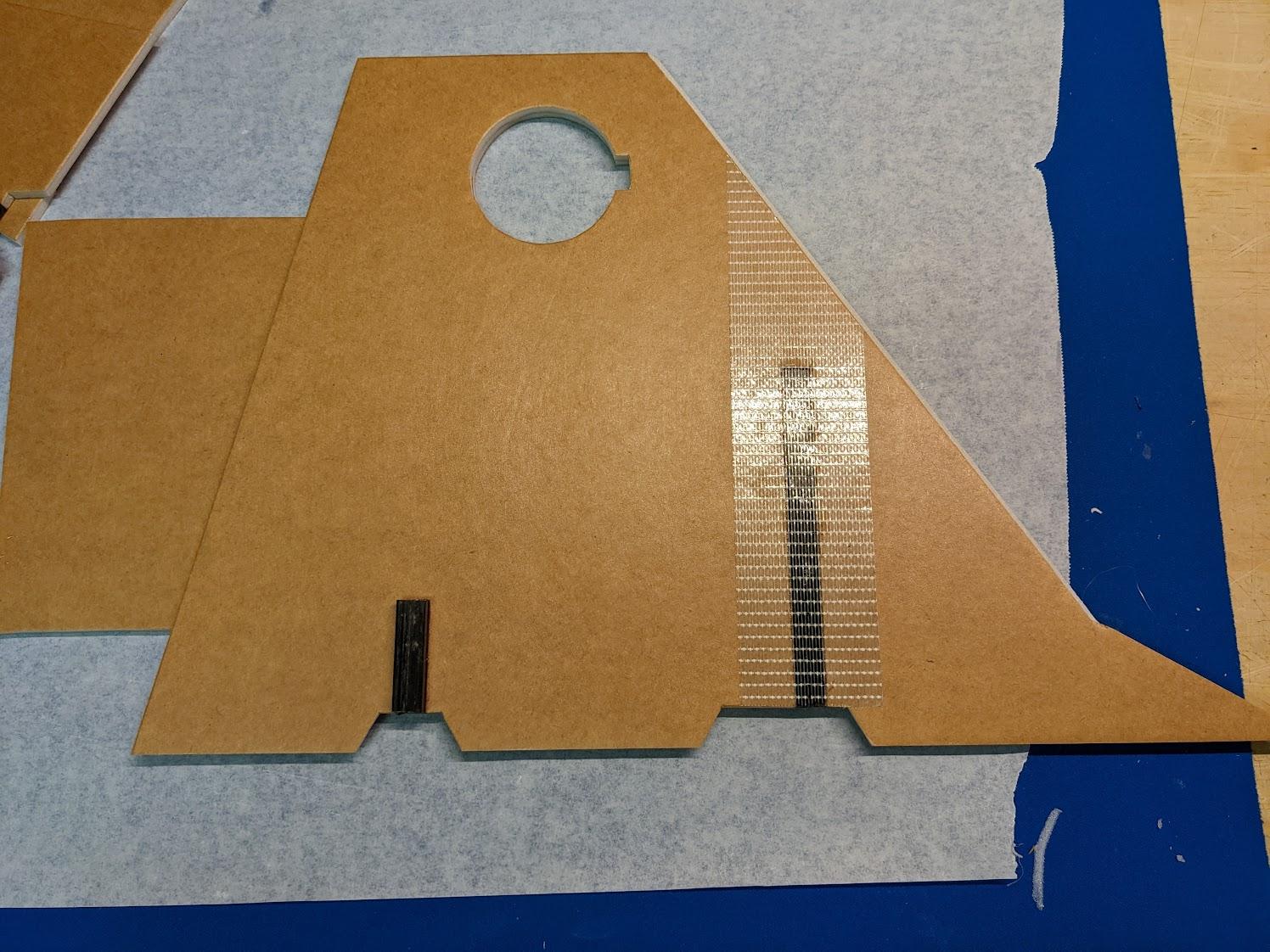
Cut the 119mm forward spars and 37mm aft spars from 10mm carbon square tube. Glue them into their slots in the wings, pressed down against the strapping tape. The aft spars will protrude from the underside since the lower wing doublers have not yet been installed.
-
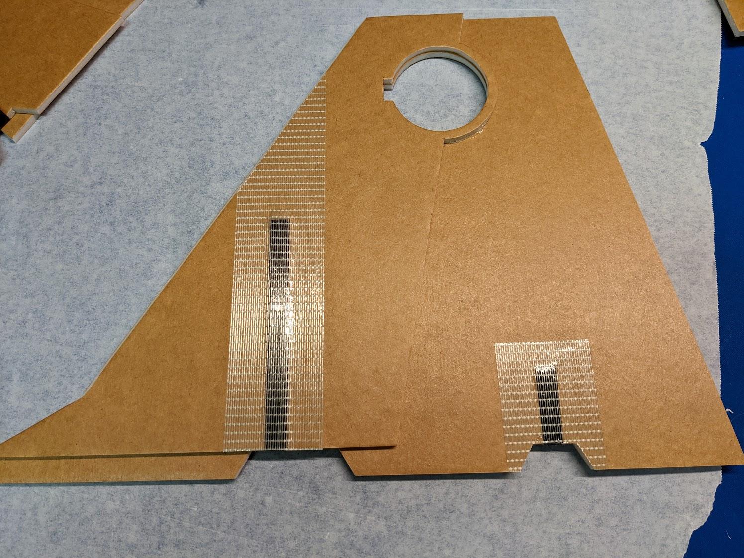
Cover the top side of the forward spars with strapping tape.
-
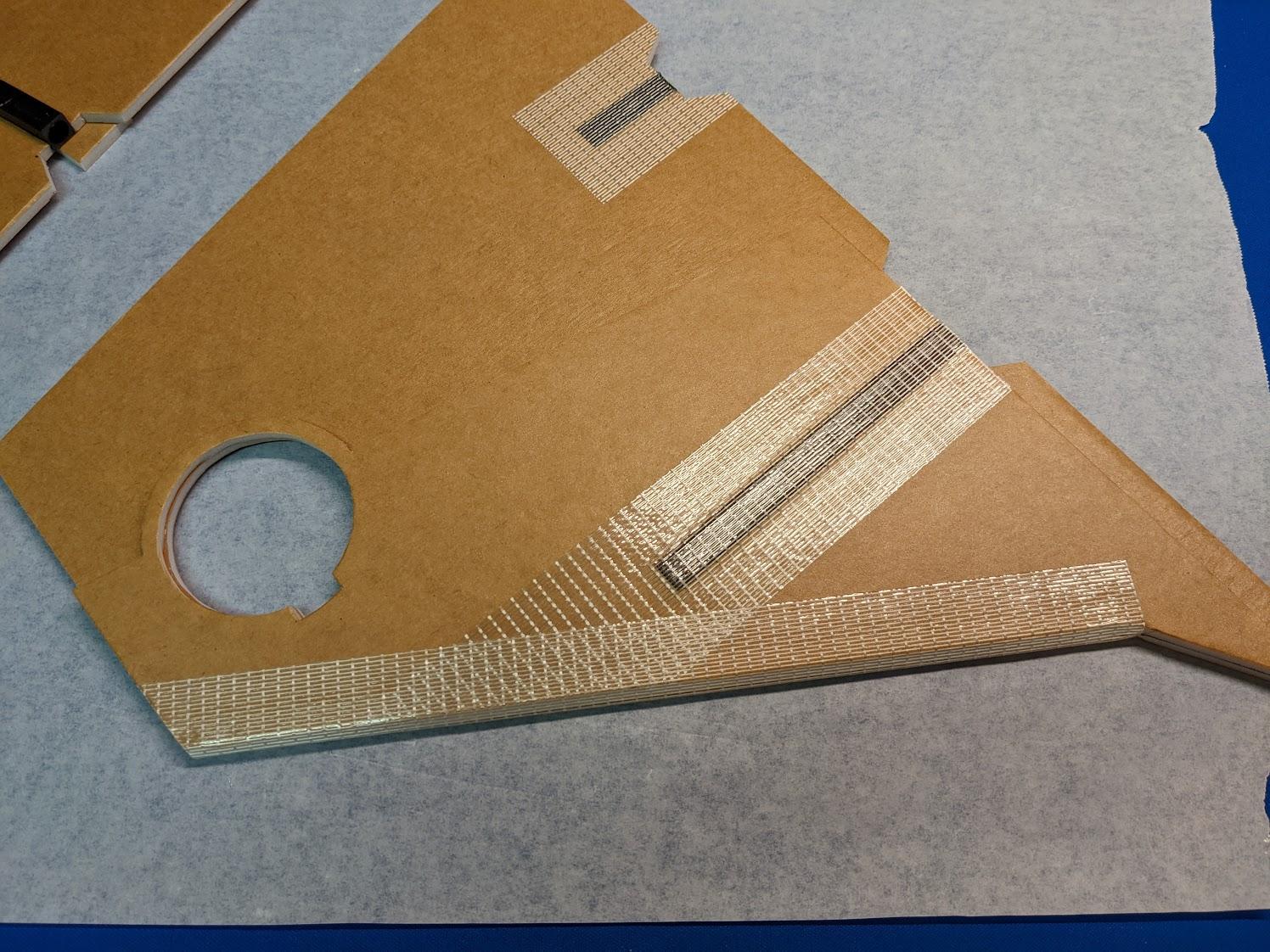
Wrap another piece of strapping tape around the beveled leading edge of each wing.
-
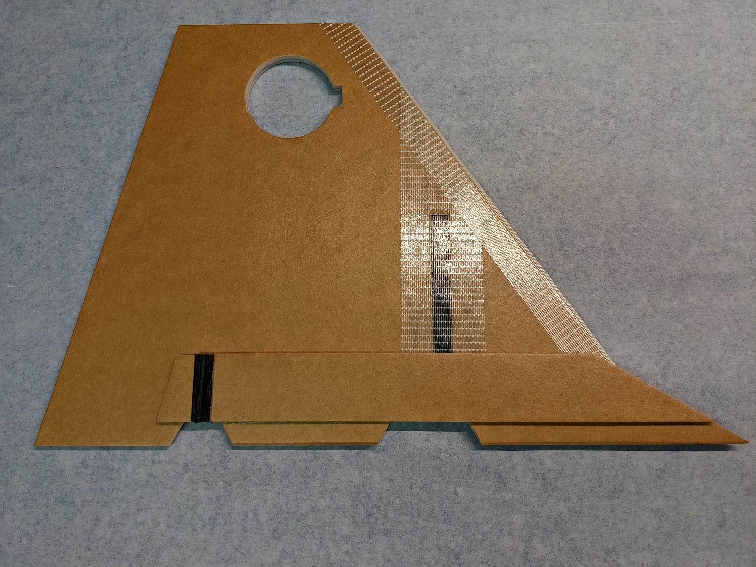
Glue the two lower wing doubler parts to the underside of each wing, surrounding the aft wing spars.
-
Cover the bottom of the aft wing spar with a piece of strapping tape.
-
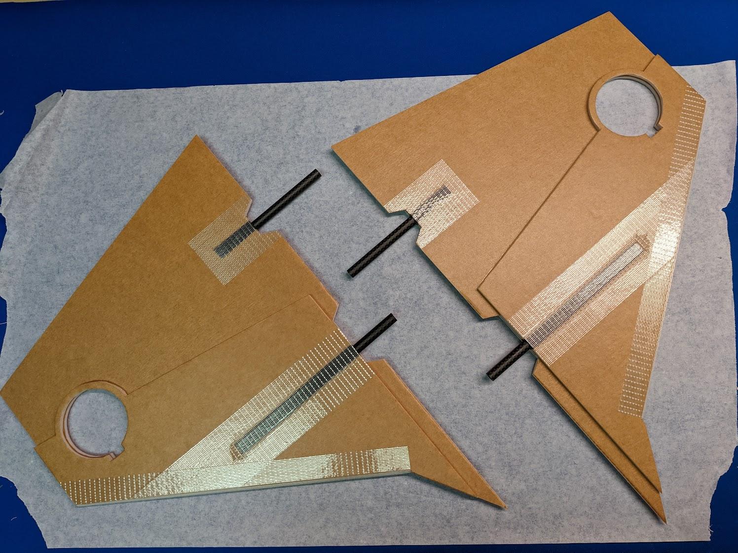
Cut the 76mm forward and 110mm aft spar joiners from 8mm carbon tube. Glue them into the wing spars using CA. The forward joiners should protrude 39mm from the edge of the wing spars, while the aft joiners should protrude 72mm from the edge of the wing spars.
-
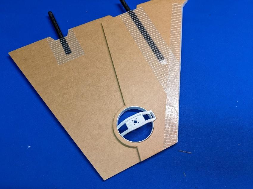
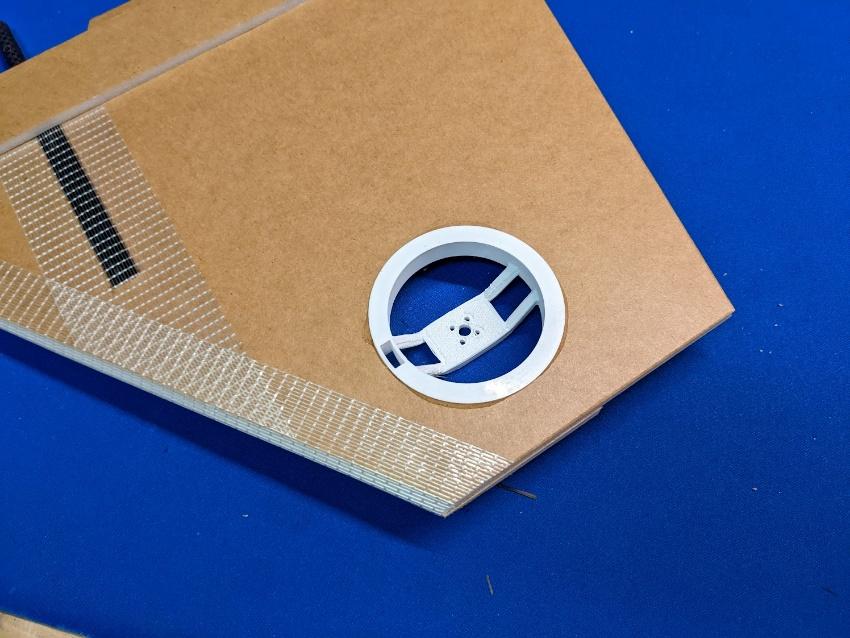
Glue the roll thruster housings into their cutouts in the wing panels.
-
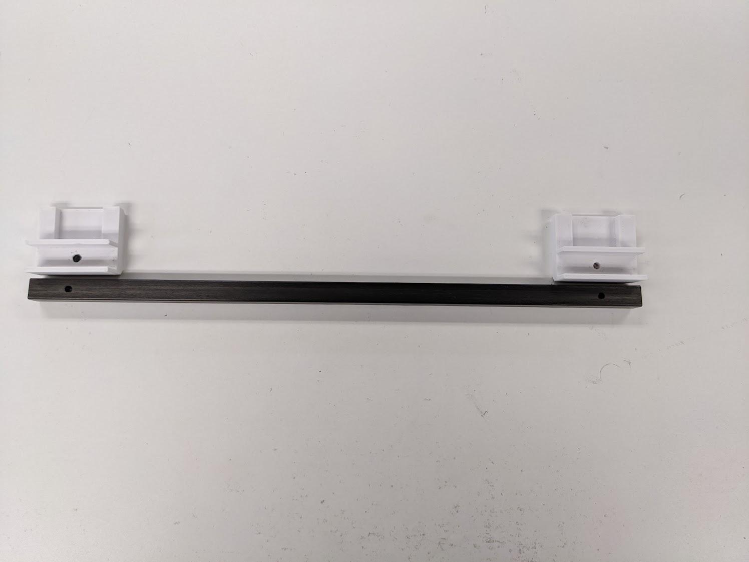
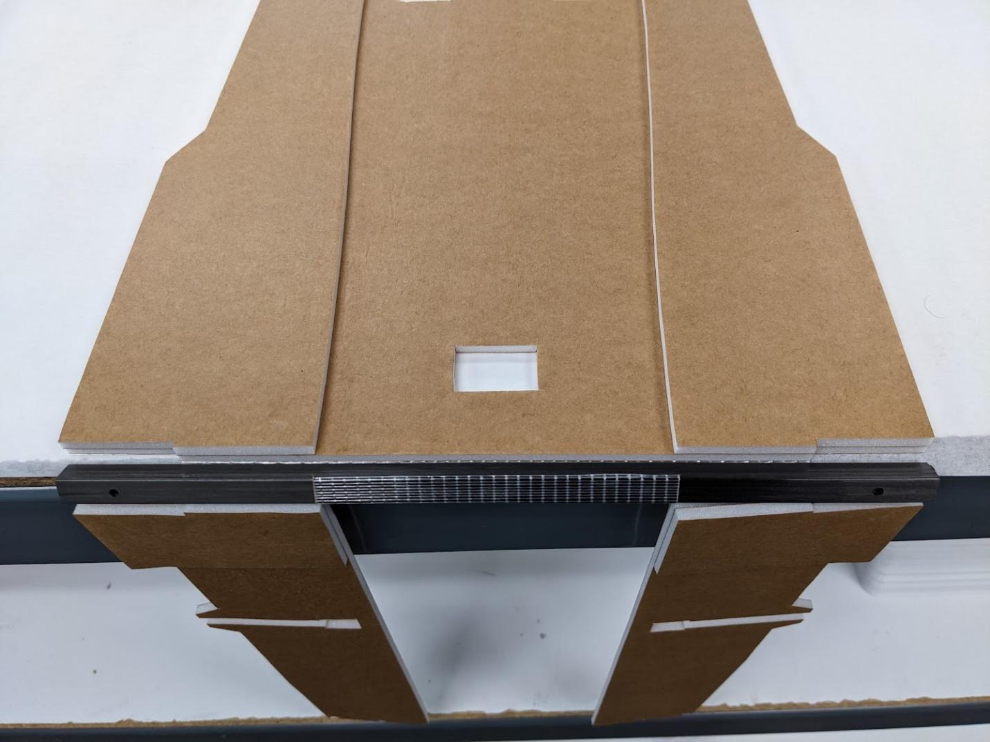
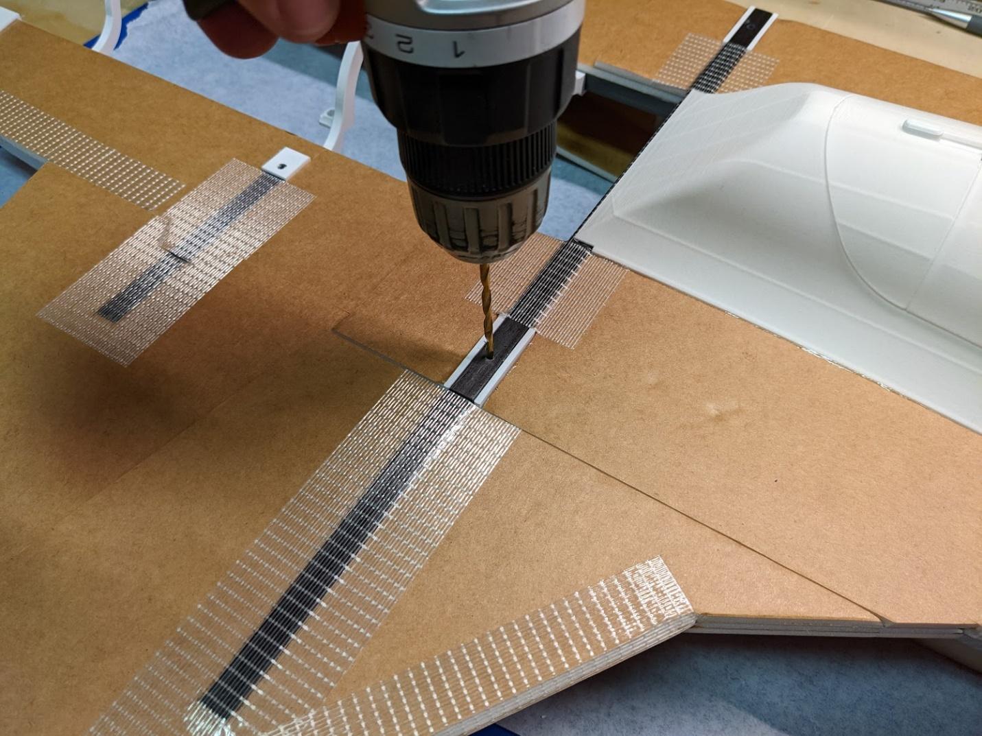
Cut the 287mm center spar section from 10mm square carbon tube. Use the main gear mounts as a guide to drill 3.2mm clearance holes for the M3 spar bolts.
-
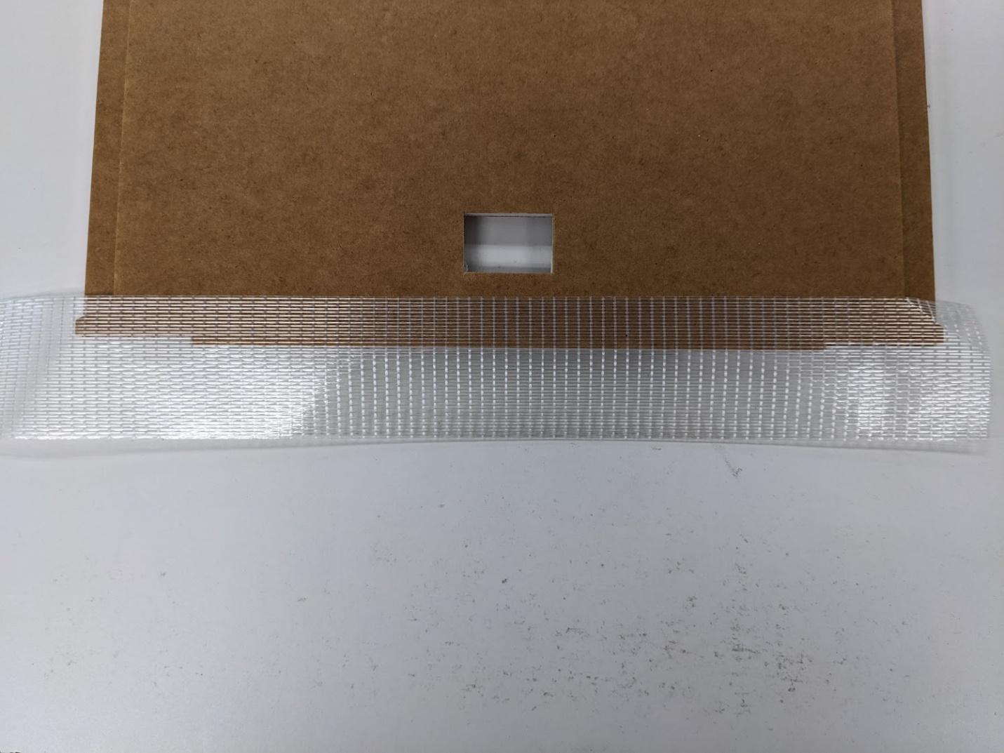
Place a piece of strapping tape along the underside of the forward center wing section.
-
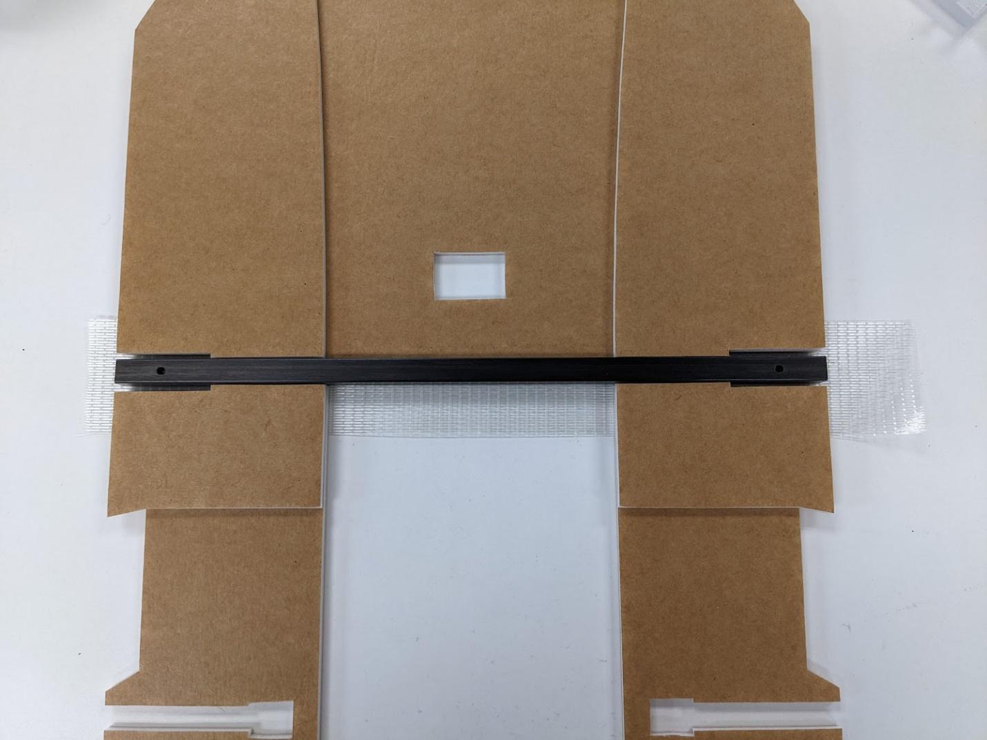
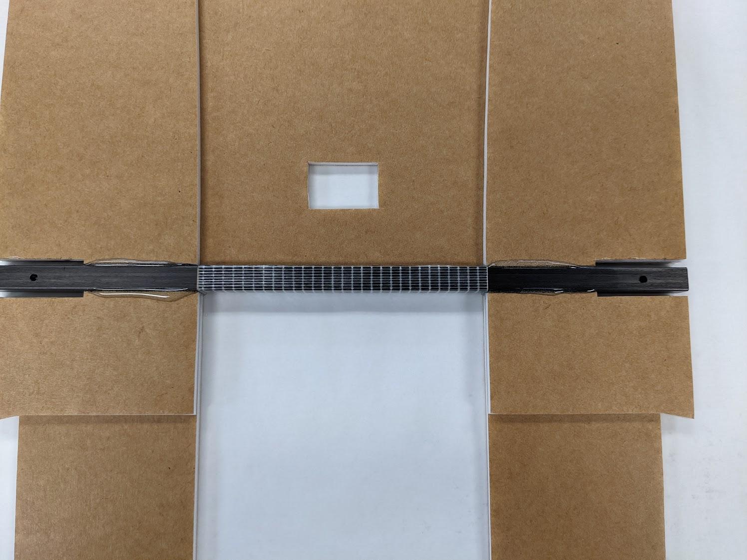
Use the strapping tape to join the forward center wing section, center spar, and aft center sections.
-
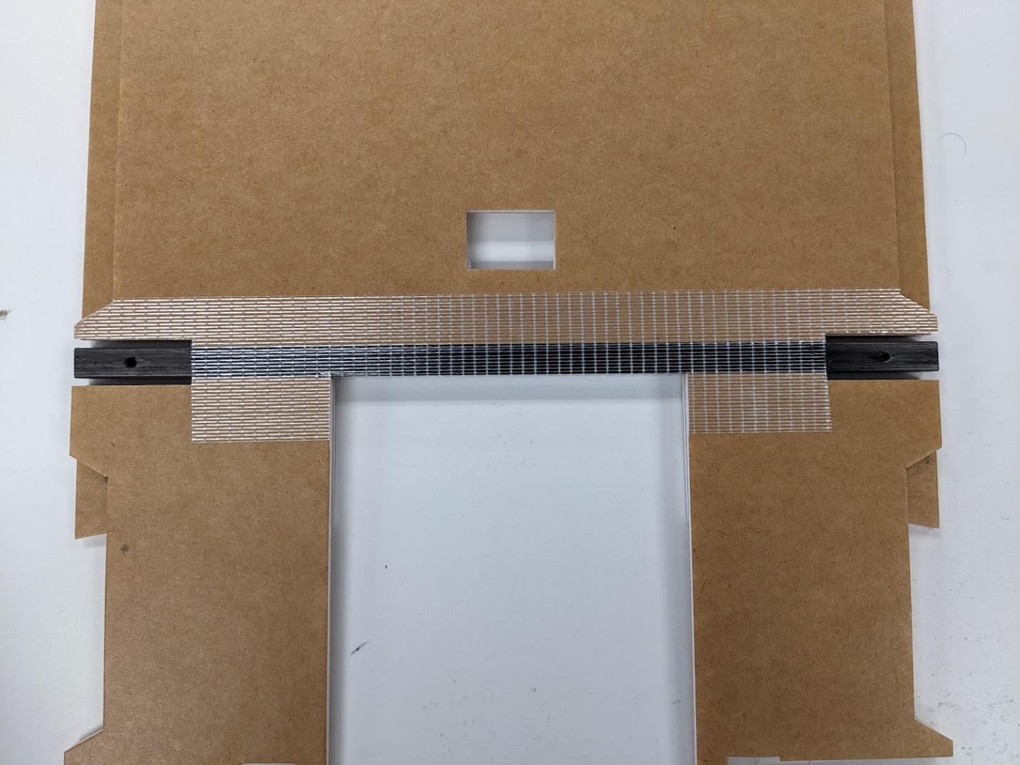
Wrap and trim the tape on the underside of the center section as shown.
-
Spread the spar and foam apart and apply epoxy to the contact surfaces. Rest the part flat while curing.
-
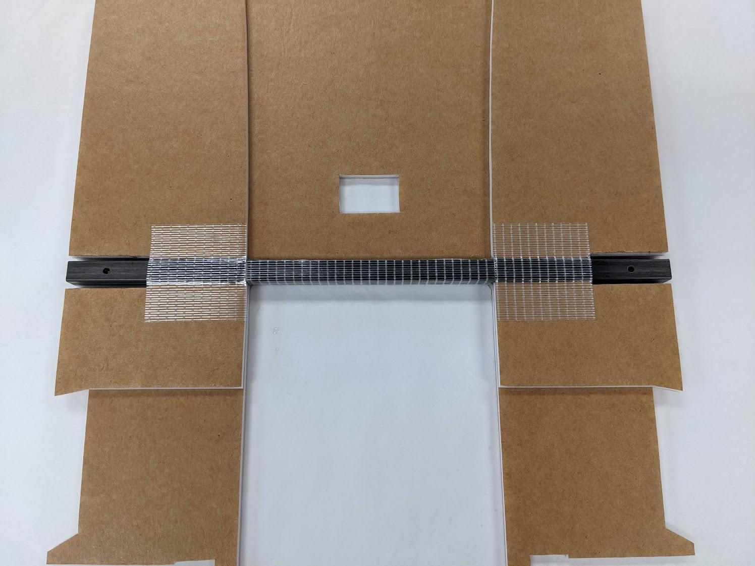
Once the glue has cured, cover the areas shown with strapping tape.
-
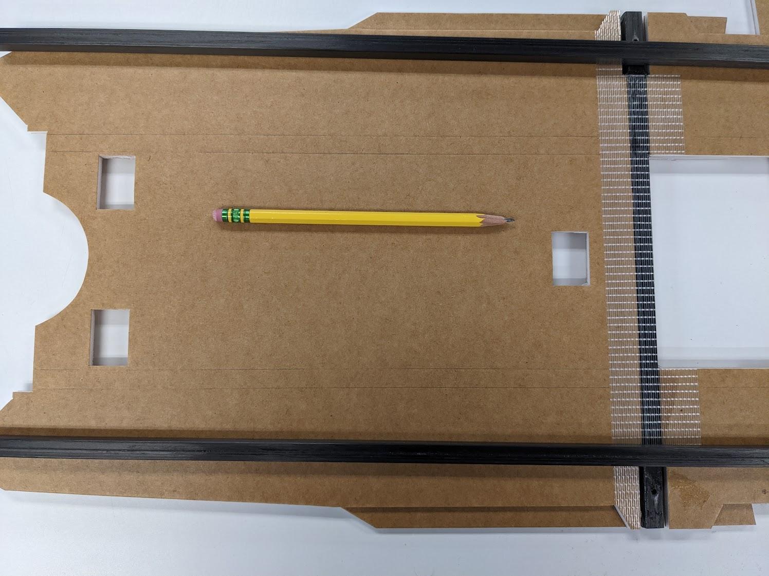
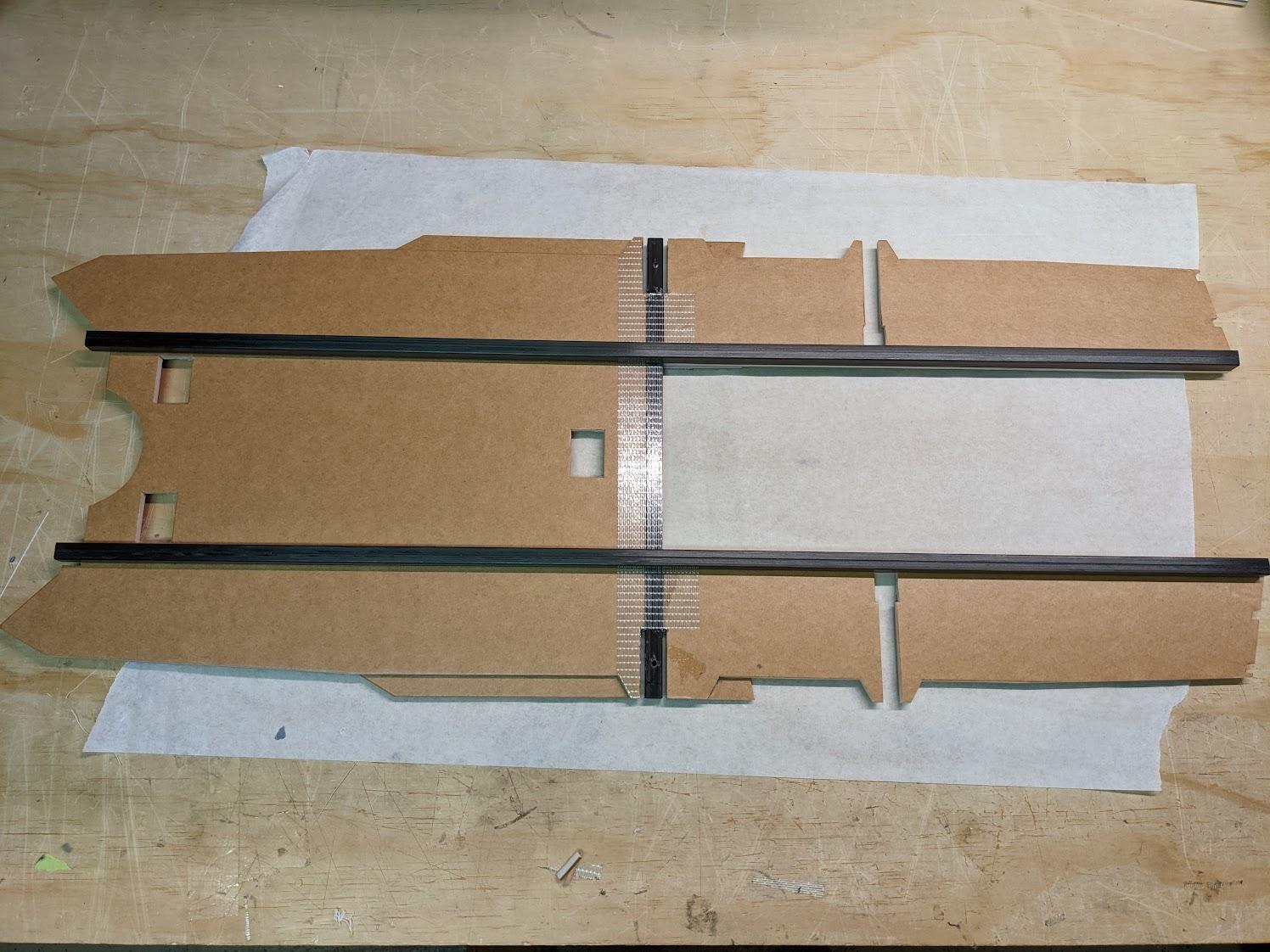
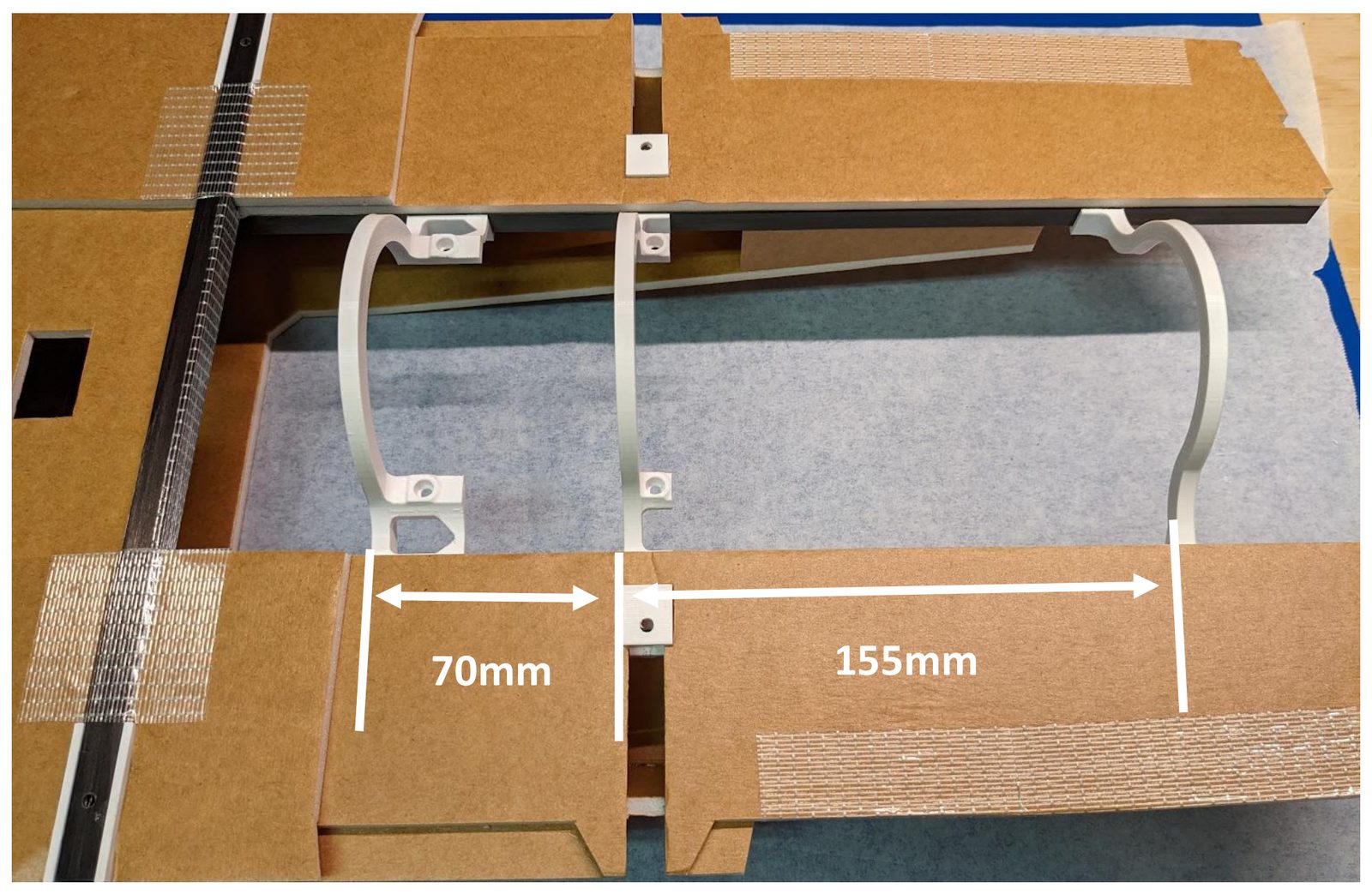
Use a pencil to mark the locations of the carbon square fuselage spars. They should be 119mm apart – flush with the edges of the cutout in the aft fuselage.
-
Use UHU-Por, Foam-Tac, or epoxy to glue the carbon fuselage spars to the underside of the assembled center section. The front of the spars should be flush with the lip at the corners of the inlets – protruding 10.5mm ahead of the cutout for the lift fan mounts.
-
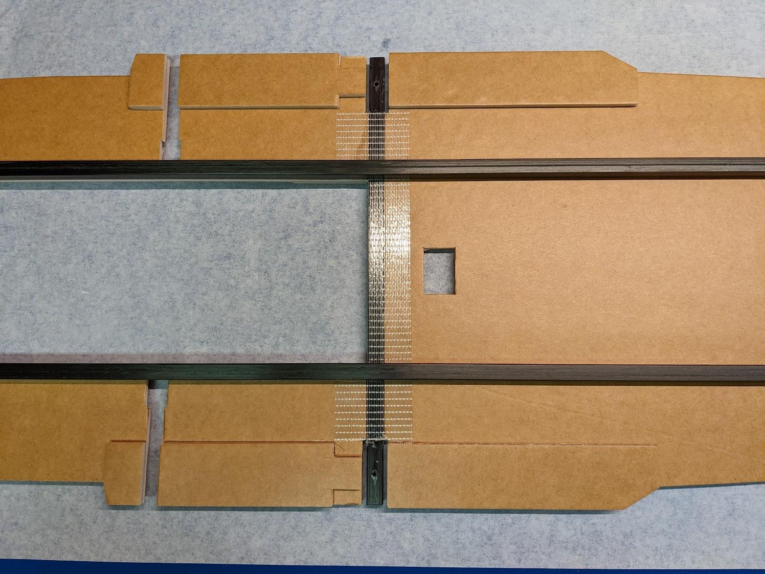
Laminate the three lower fuselage doubler components to each side of the underside of the center section as shown.
-
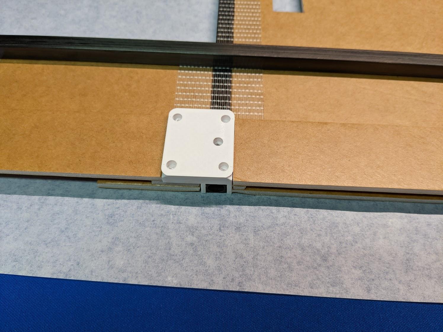
Use epoxy to attach the main gear mounts to the spar and underside of the center section.
Lower fuselage assembly
-
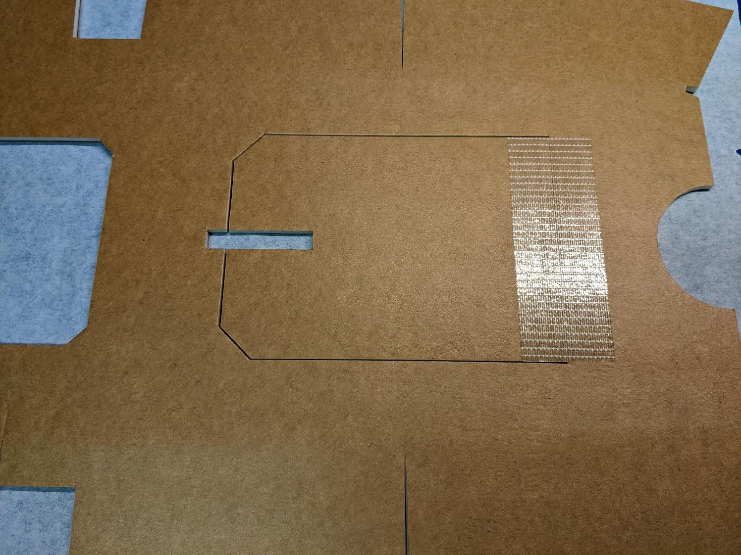
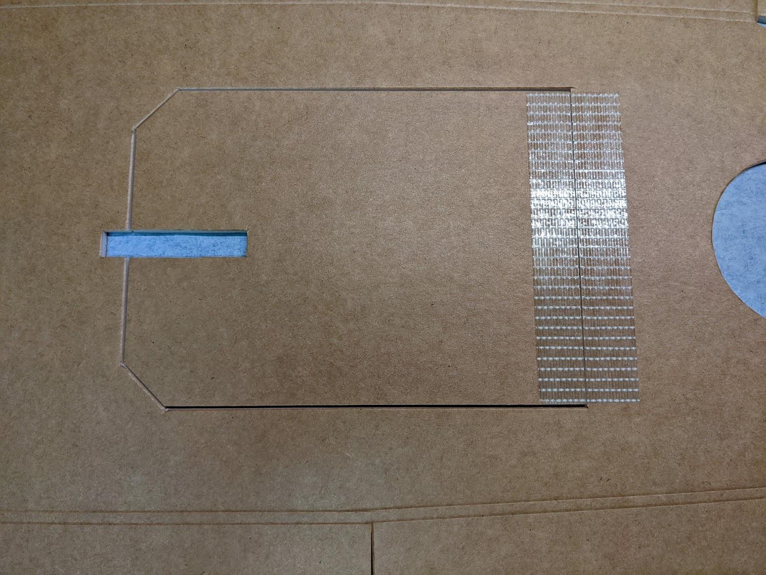
Trim the hatch cutout as needed. Hinge it on the underside with a piece of strapping tape.
-
Fold the hatch over, then hinge the inner side with strapping tape as well.
-
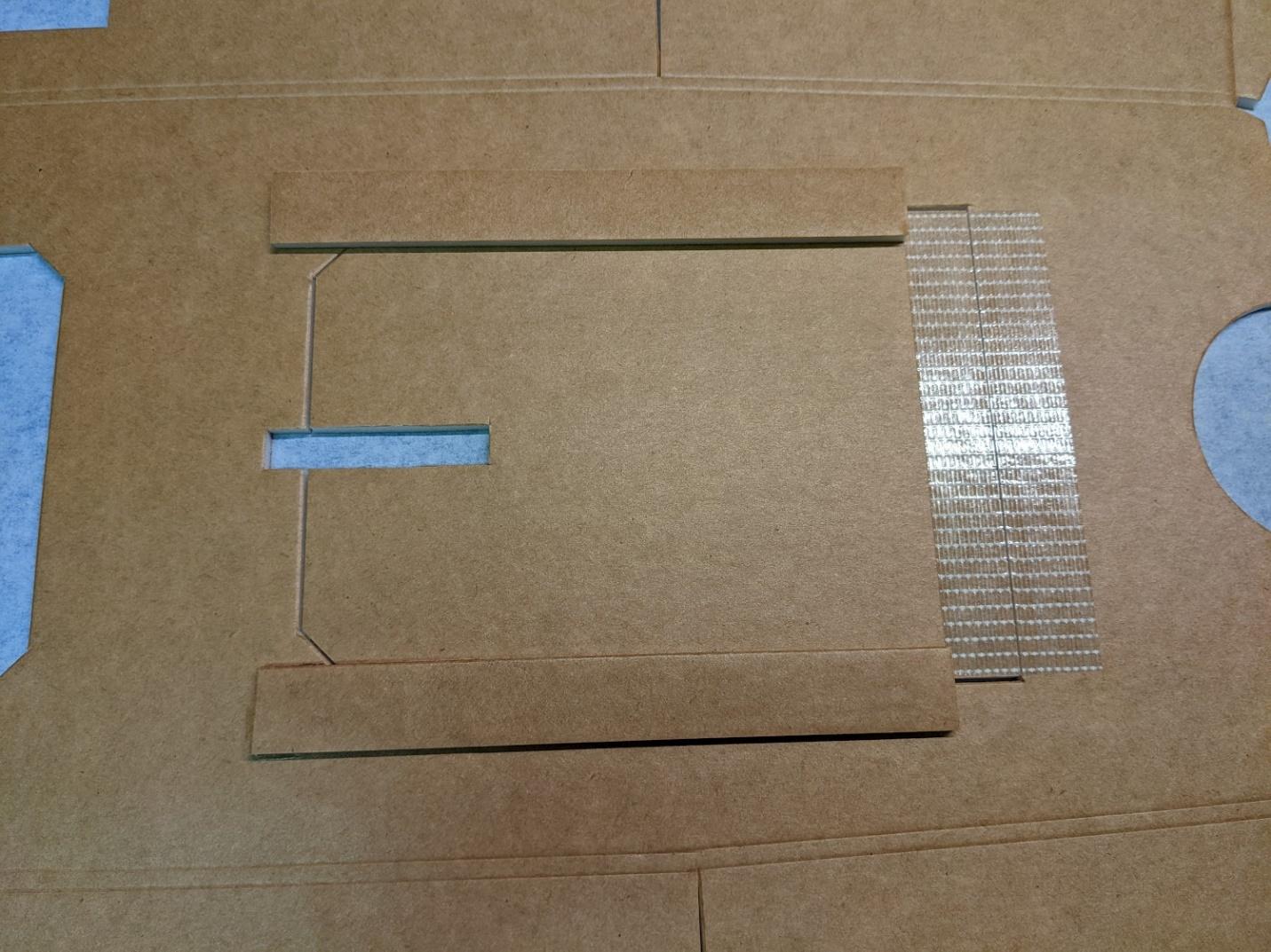
Add some scrap strips of foam to the inside of the hatch to support it when closed. Be sure to only glue these strips to the lower fuselage shell, not to the hatch itself.
-
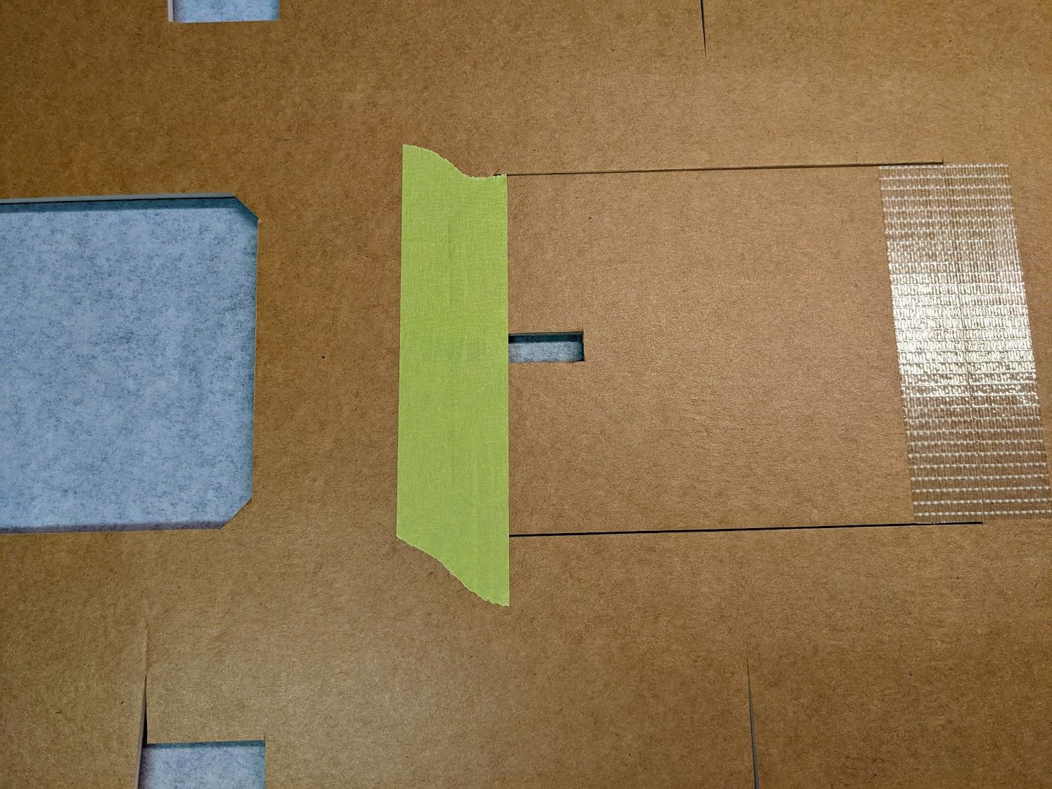
Keep the hatch closed for now with a strip of masking tape on the outside.
-
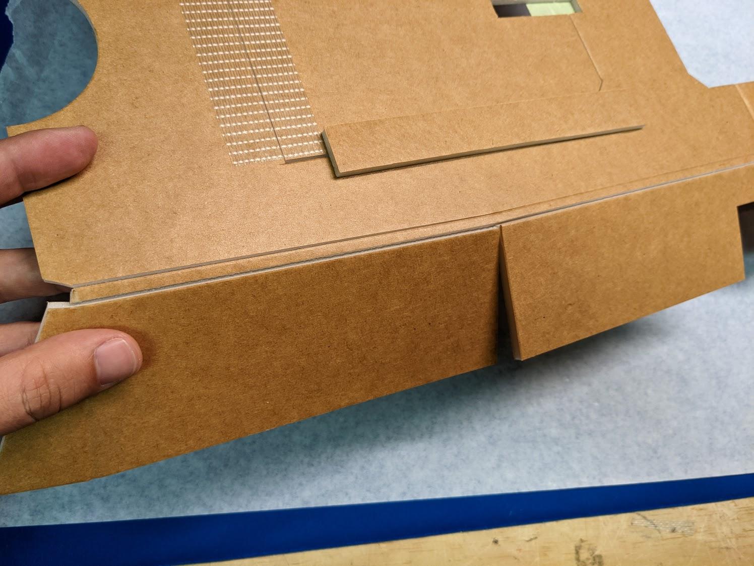
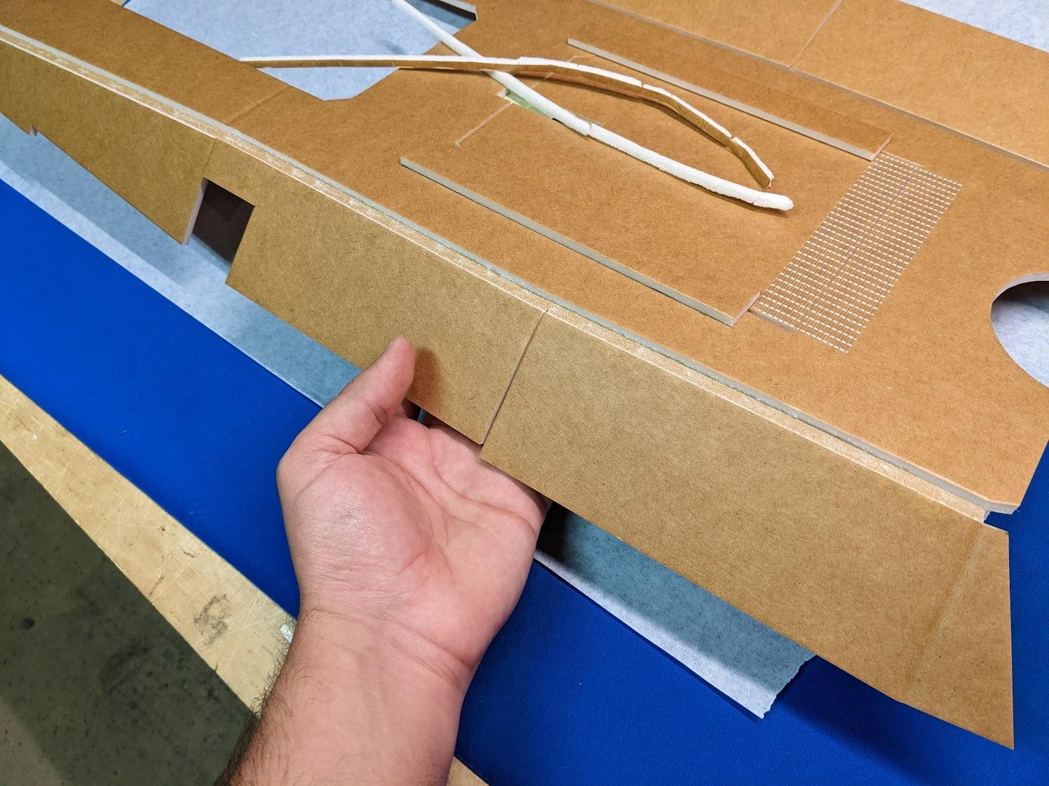
Carefully peel away the foam interior strips along the seams between the sides and bottom of the lower fuselage shell.
-
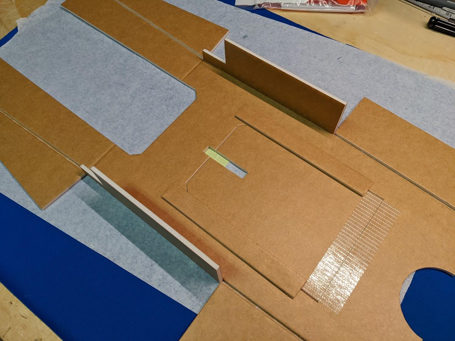
Use hot glue to fix the middle side panels upright, perpendicular to the bottom. The edges of the side panels should rest beside the bottom panel, not on top of it.
-
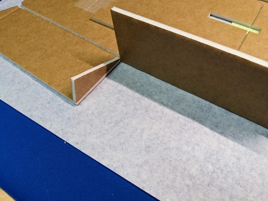
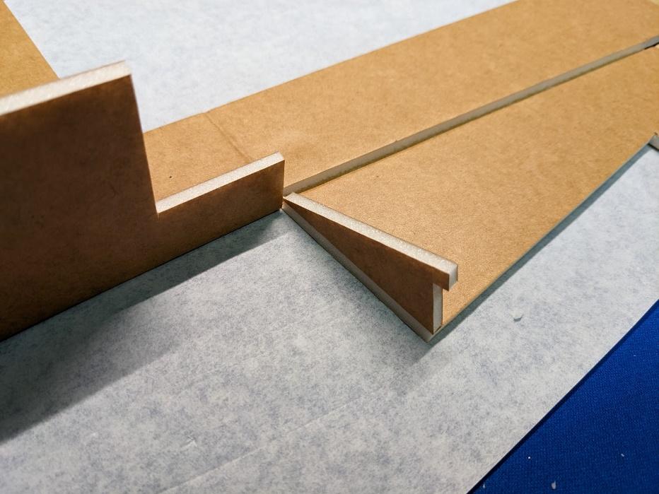
Glue the solid triangular wedges to the aft edges of the front side panels, and the notched triangular wedges to the forward edges of the aft side panels.
-
Fold the forward side panels into place and attach with hot glue, using the triangular wedges to set the angle. Use a straightedge to press a crease into the inlet portions in order to bend them inwards.
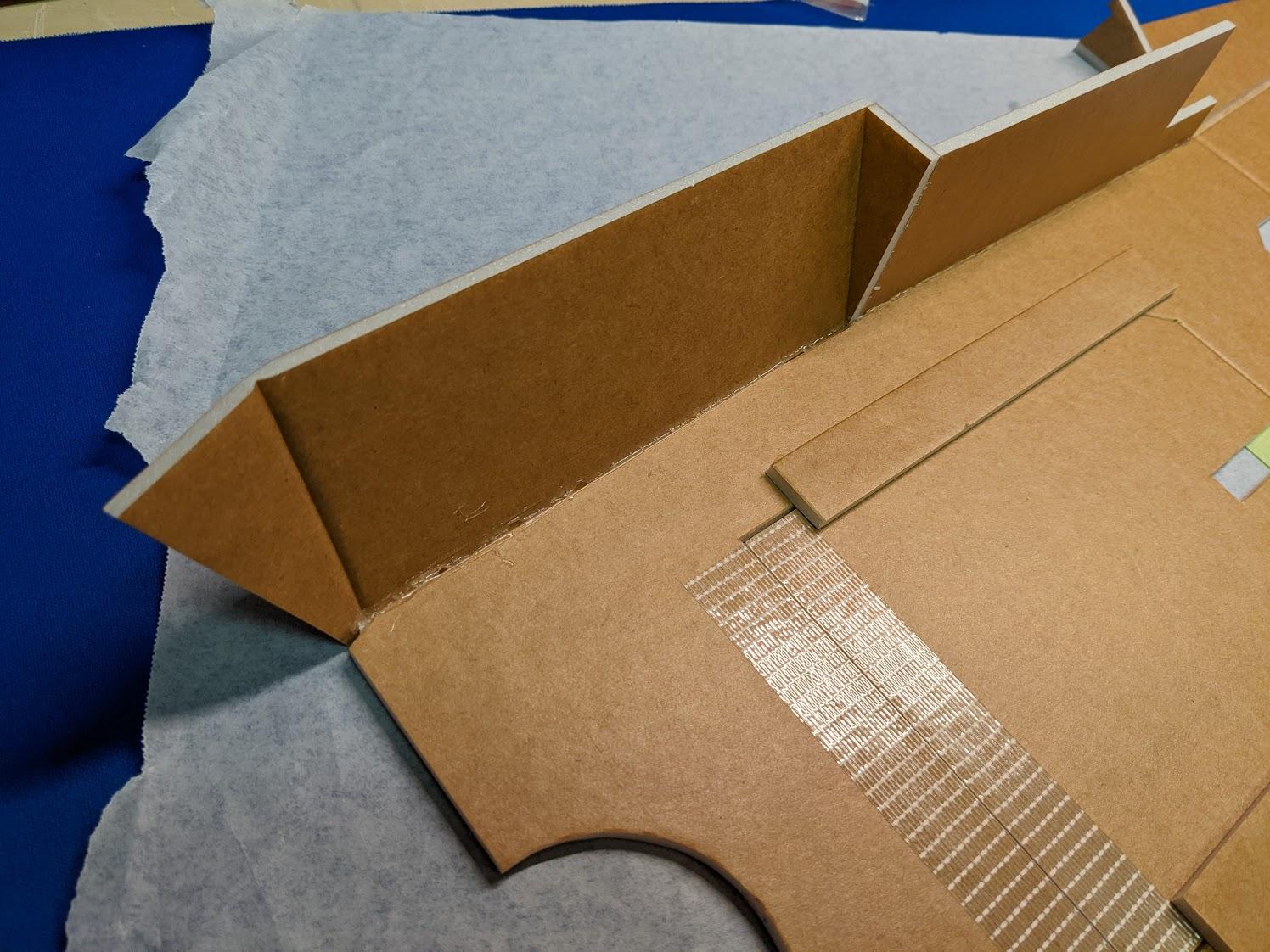
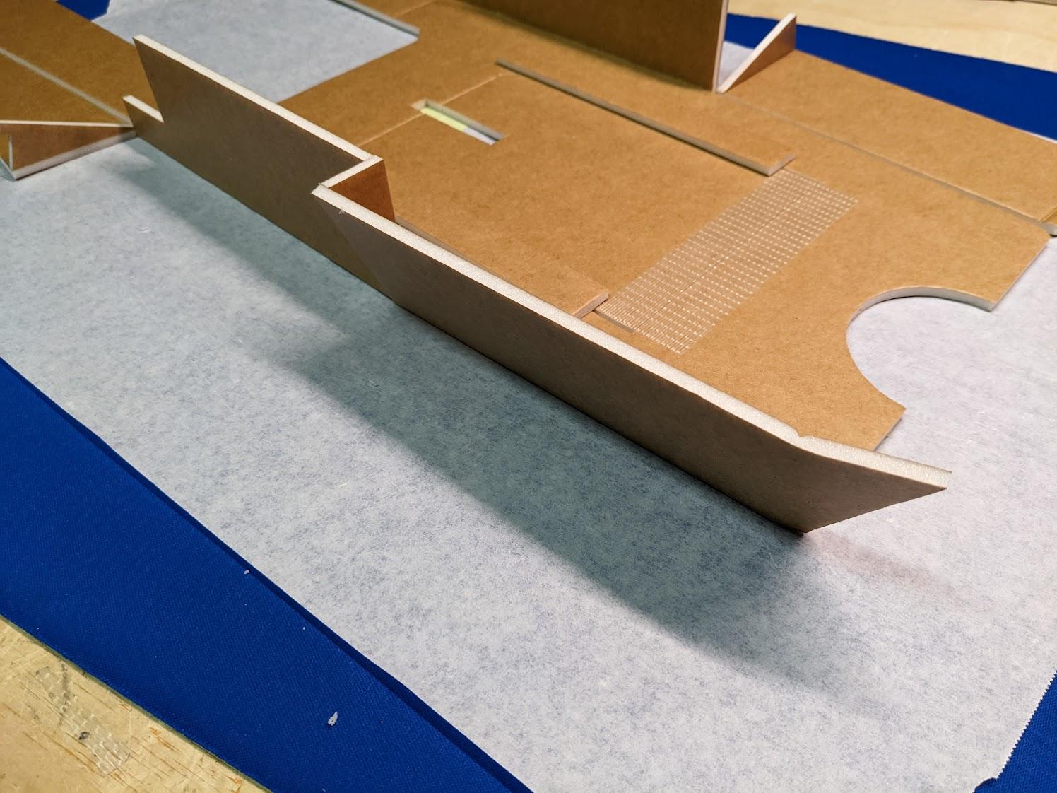
-
Fold the aft side panels into place and attach with hot glue, using the triangular wedges to set the angle. Use a straightedge to press a crease where the aft and middle sections meet such that the entire assembly can be placed flat.
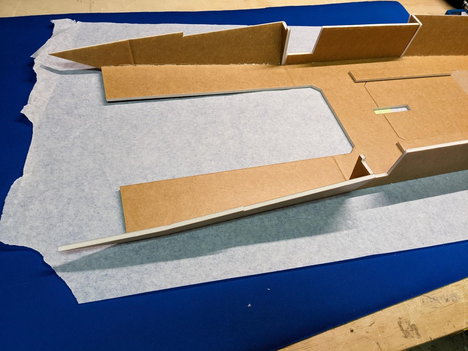

-
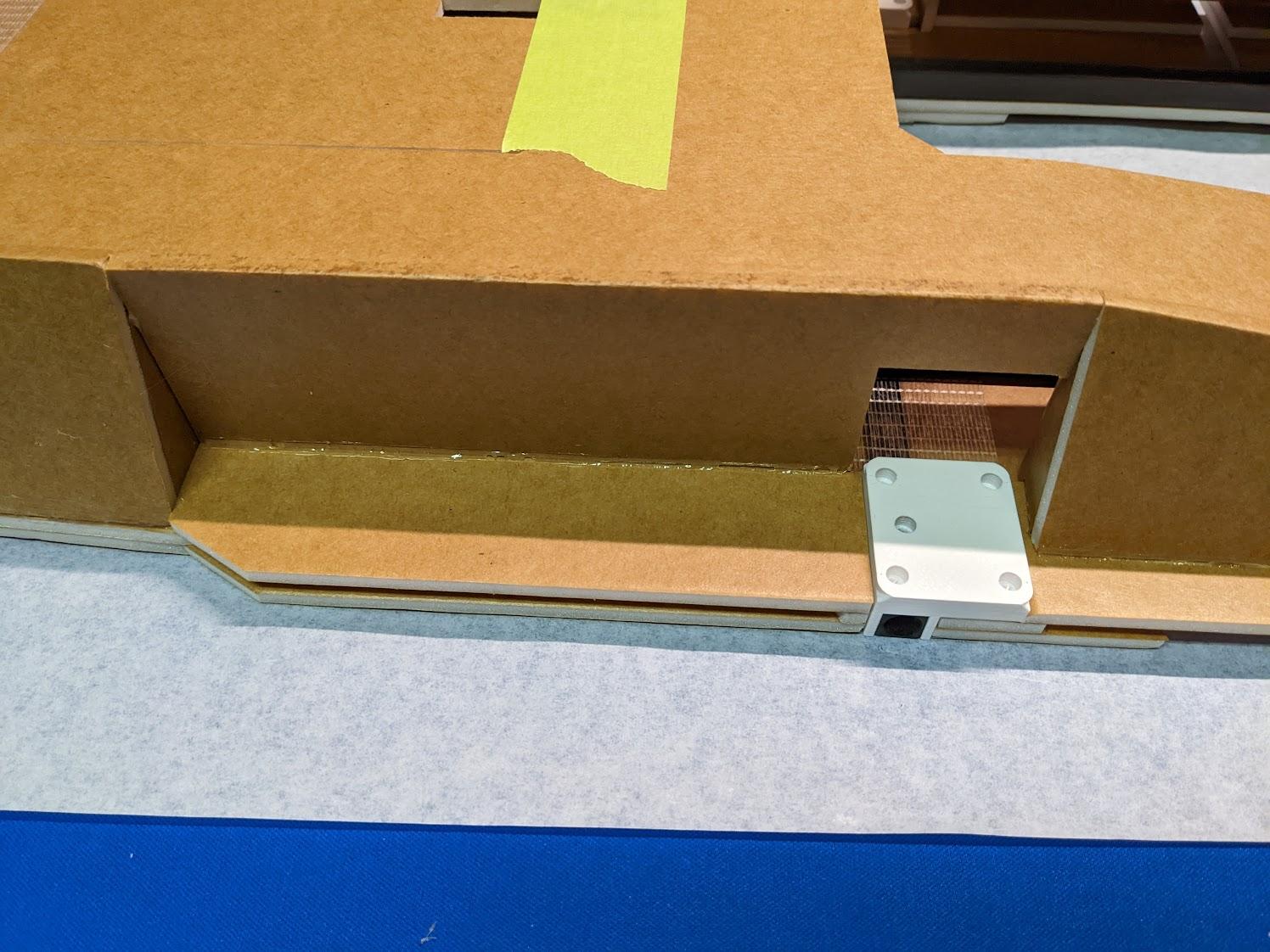
Glue the completed lower fuselage shell to the underside of the center section assembly.
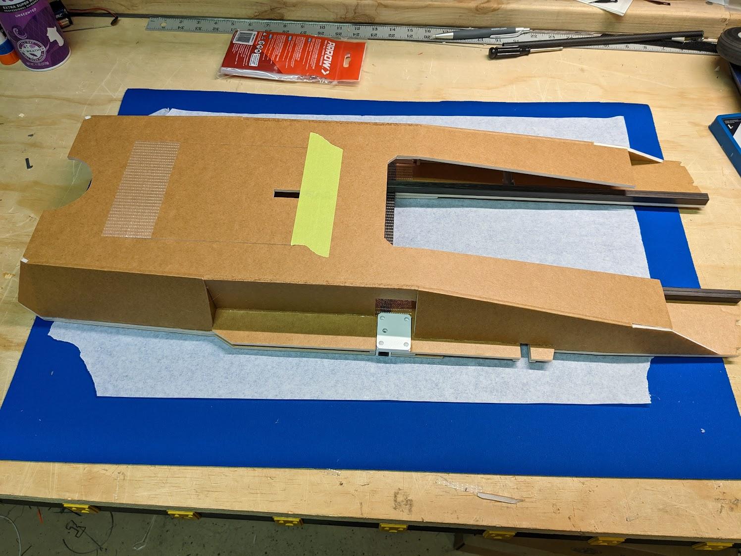
-
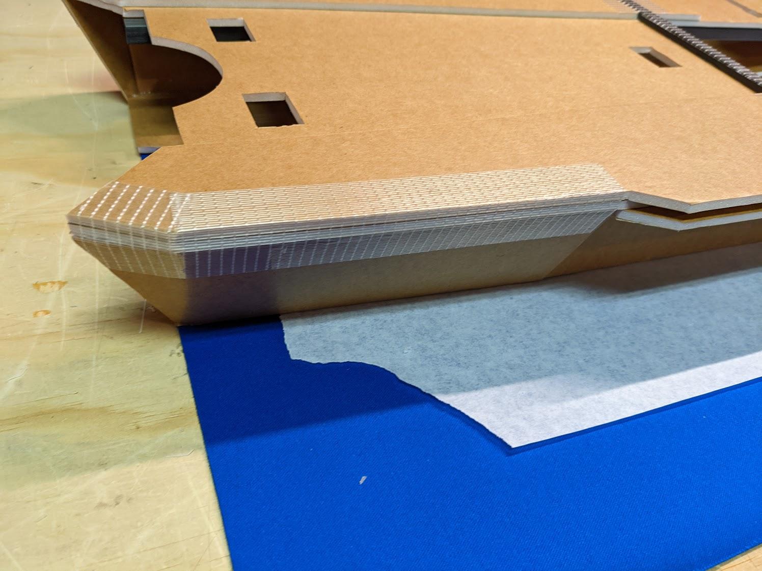
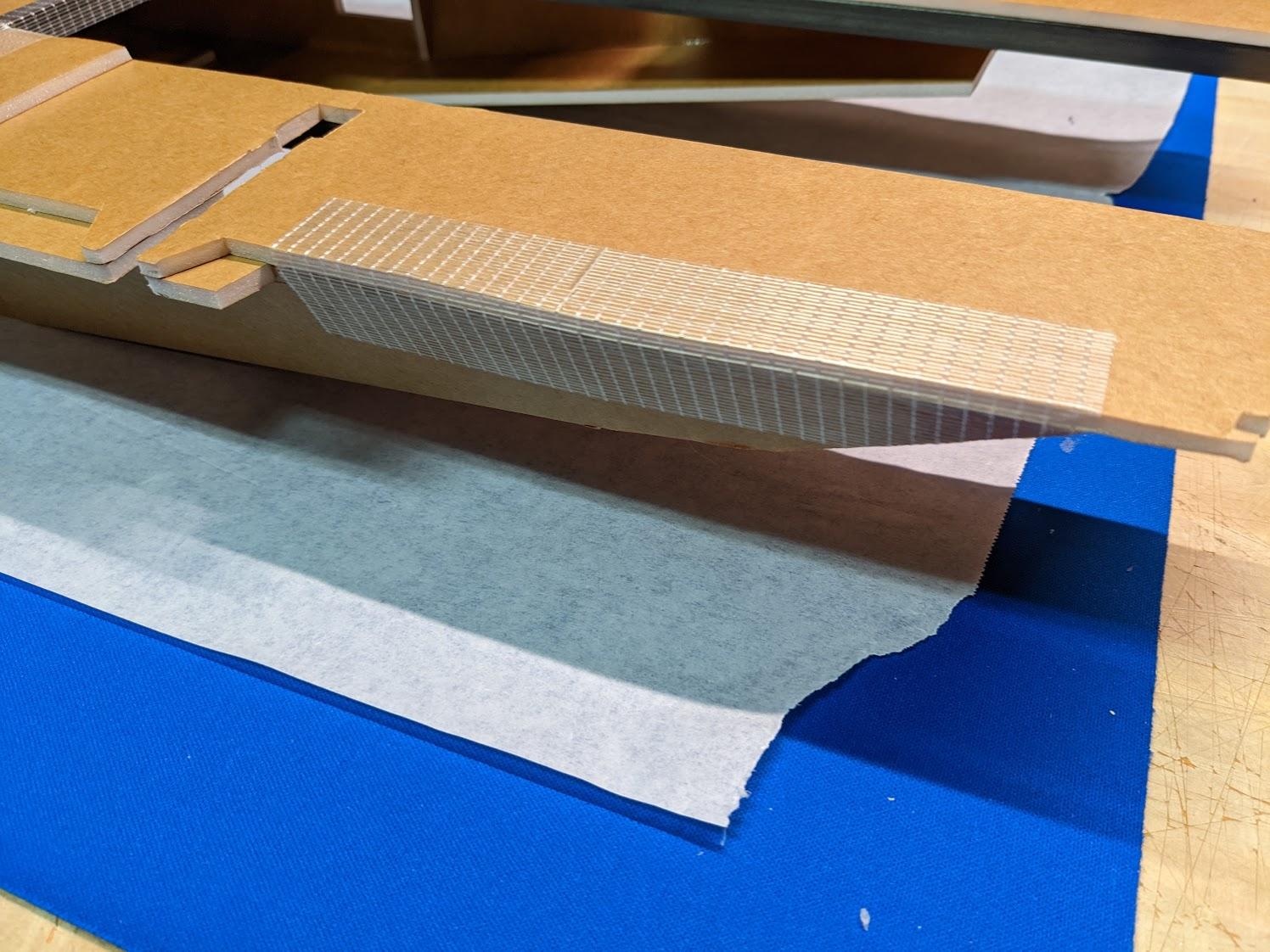
Reinforce the forward and aft edges with strapping tape.
-
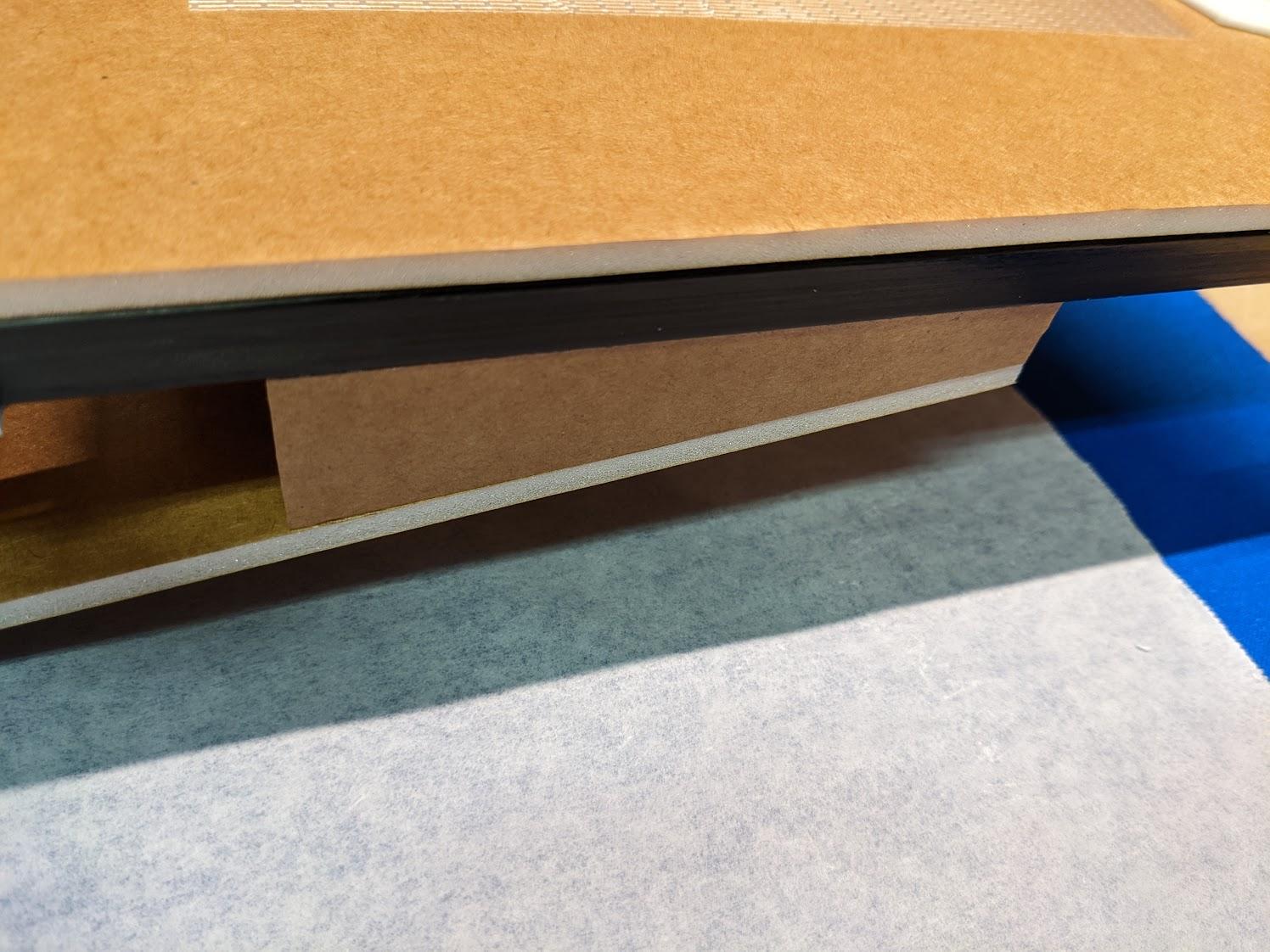
Install the spacer wedges between the rear of the lower fuselage and the carbon fuselage spars.
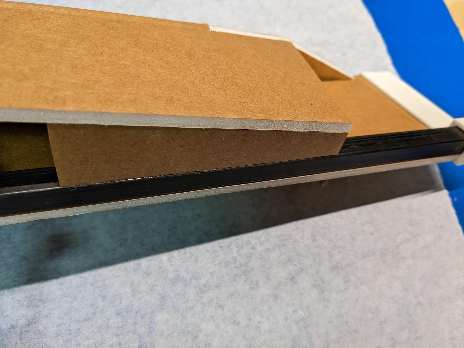
Upper fuselage assembly
-
Use CA to glue the 3BSM mounts and rear brace to the carbon fuselage spars.
-
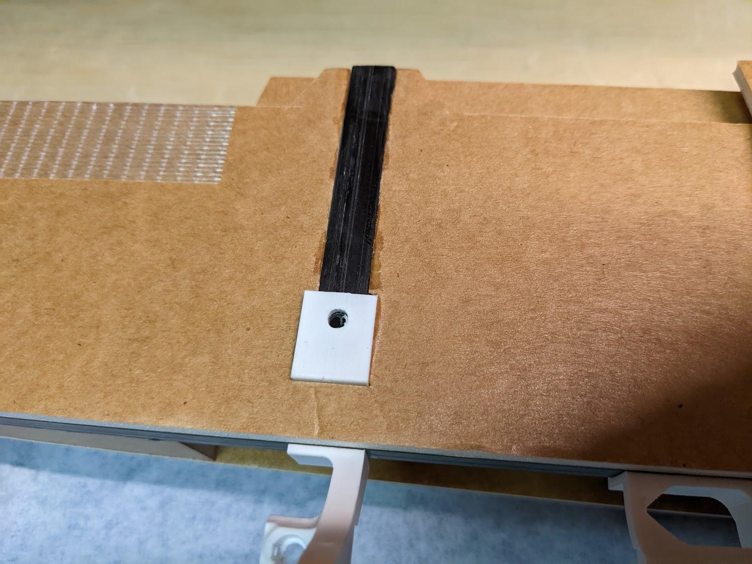
Cut the 72mm rear spar receptacles from 10mm square carbon tube and glue with epoxy.
-
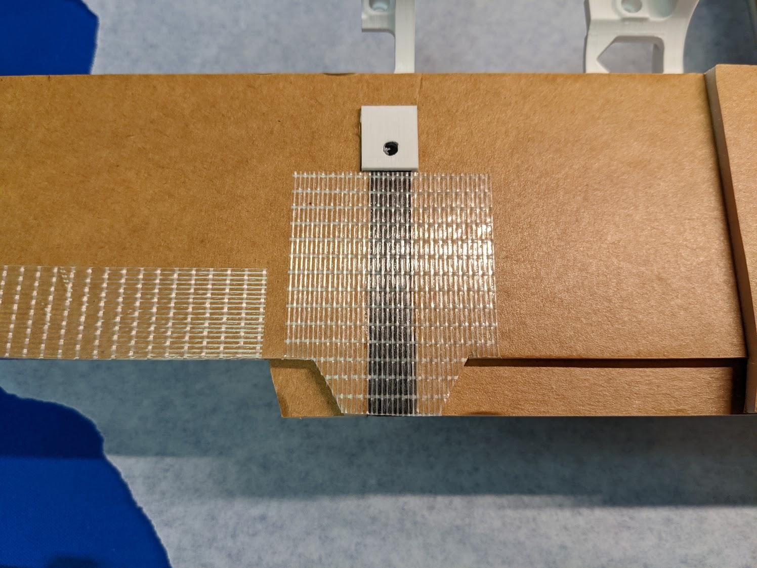
Cover the rear spar receptacles with strapping tape and trim as necessary.
-
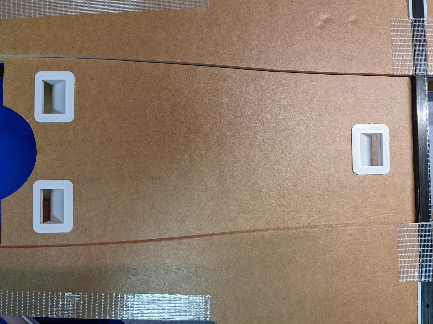
Glue the cooling vents into their holes in the center section.
-
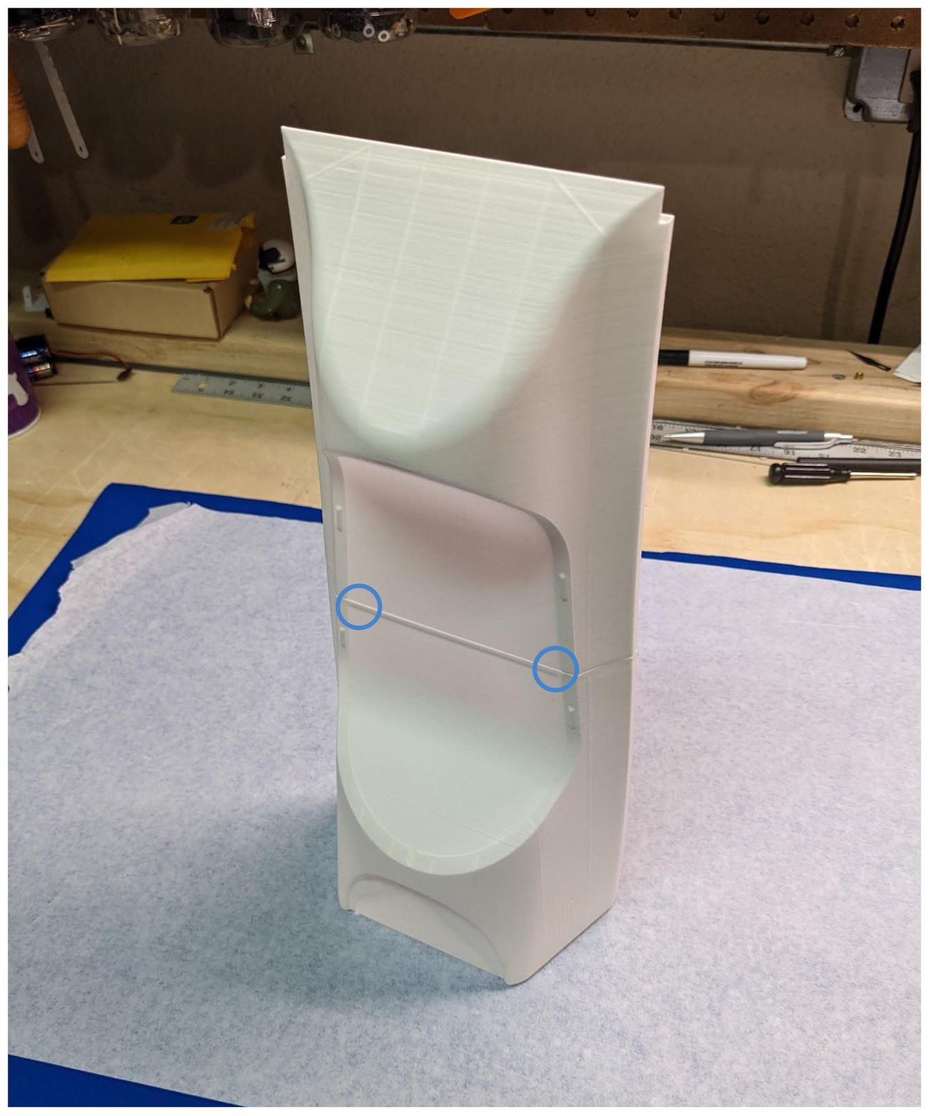
Use CA to glue together the two upper fuselage sections. Trim the corners shown in order for the parts to interlock properly.
-
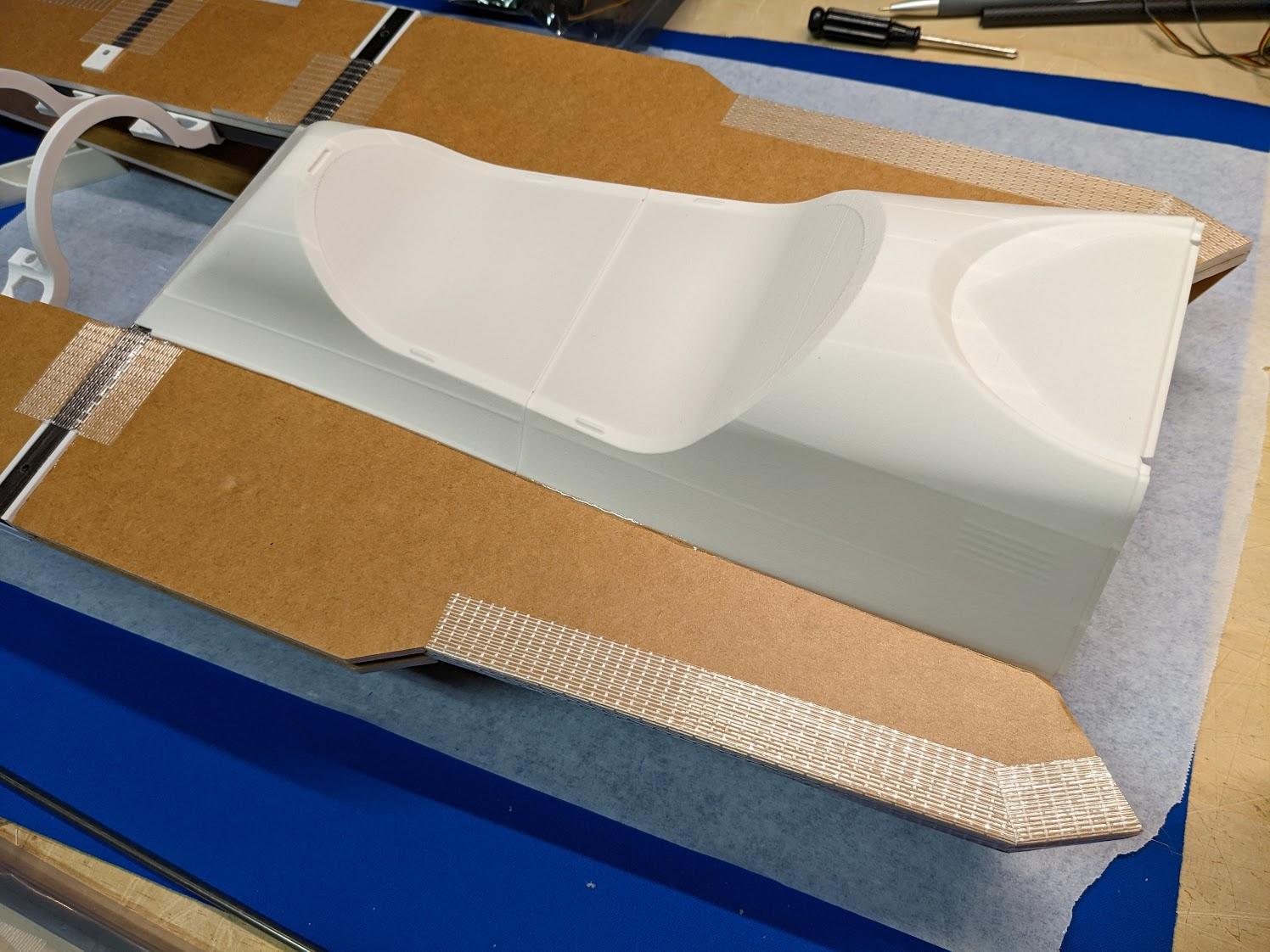
Use epoxy to glue the upper fuselage to the center section.
-
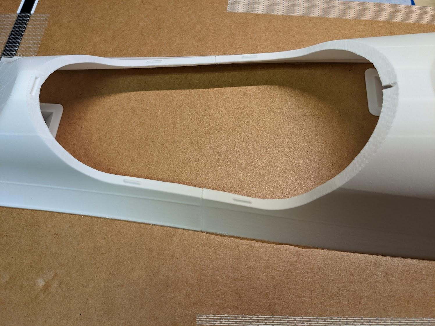
Use a sharp hobby knife to carefully cut away the hatch opening.
-
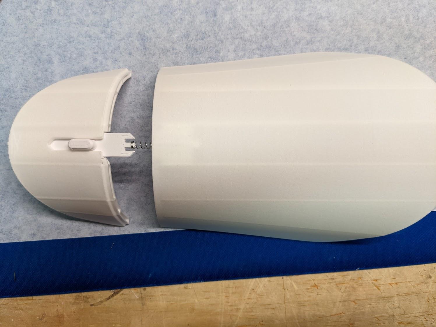
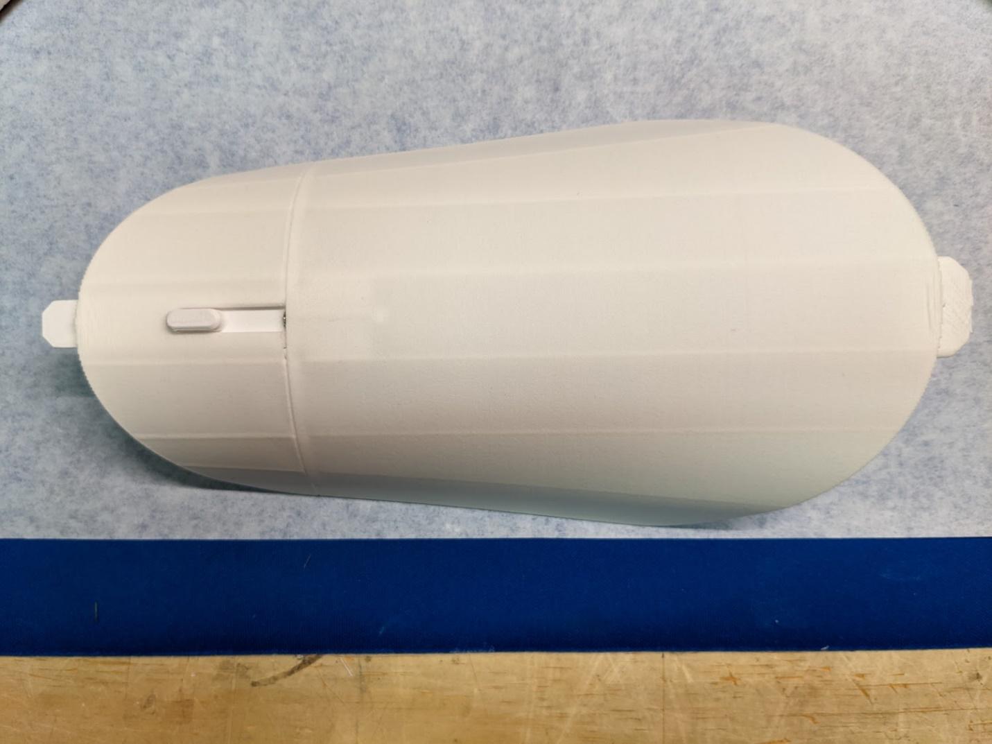
Insert a pen spring and the hatch latch into the forward hatch section. Then, glue the two sections of the hatch together. Ensure that the hatch latch can slide freely.
-
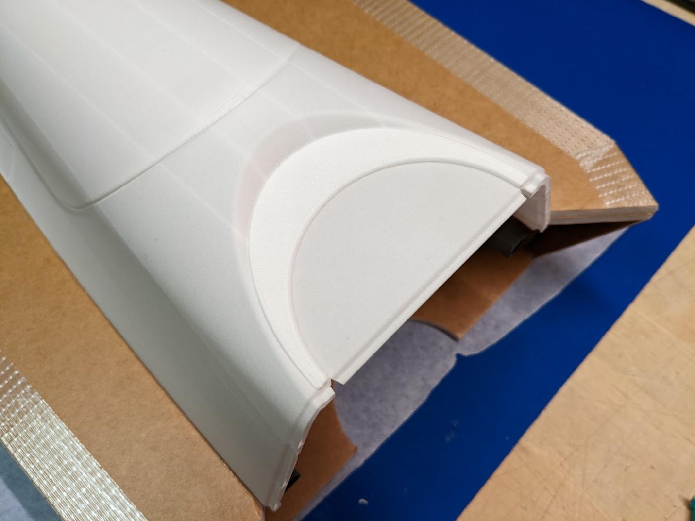
Glue the upper fan doubler to the forward section of the upper fuselage.
-
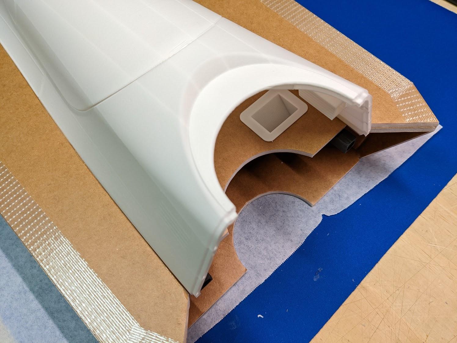
Trim the circular fan cutout area.
-
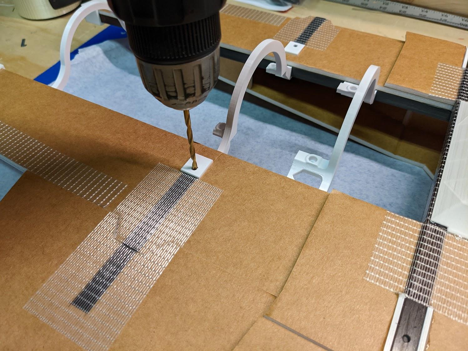
Dry fit the wings and drill clearance holes for the forward and aft spar bolts.
-
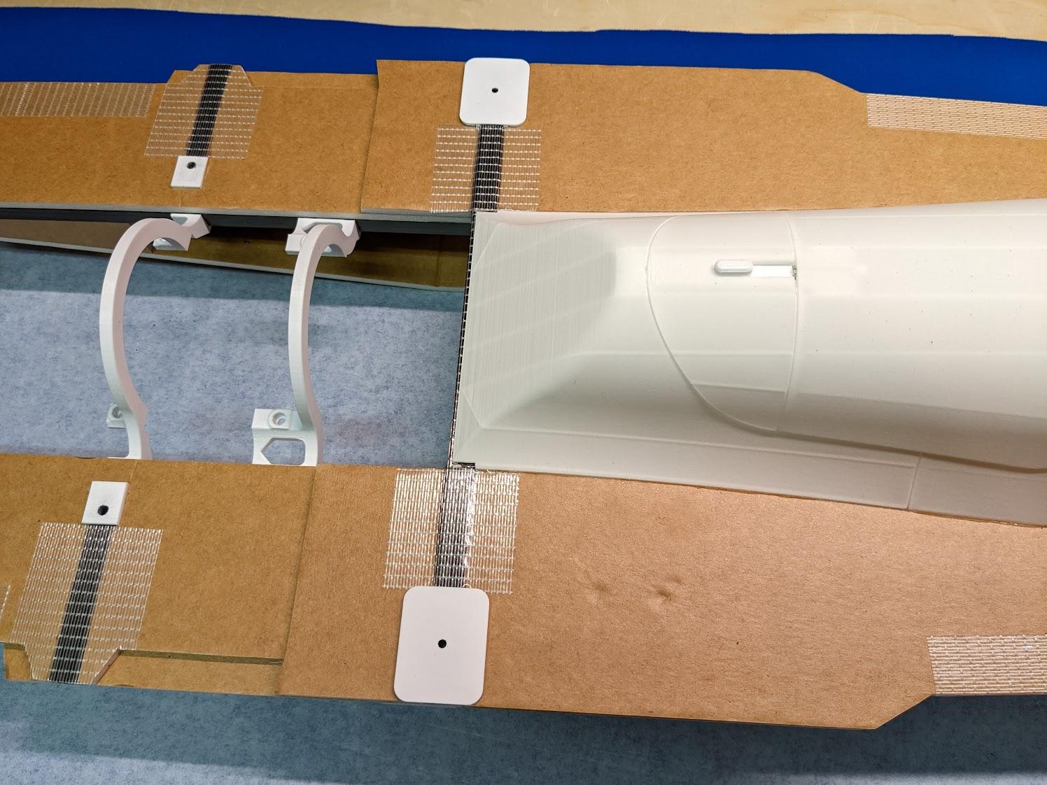
Glue the top reinforcement plates above the landing gear mounts on either side.
-
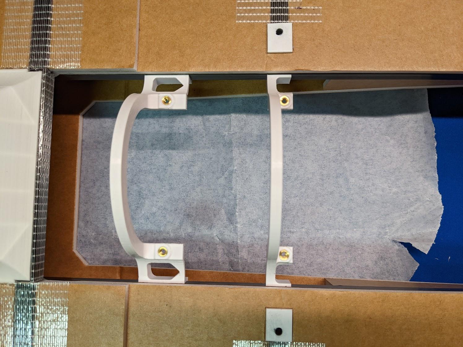
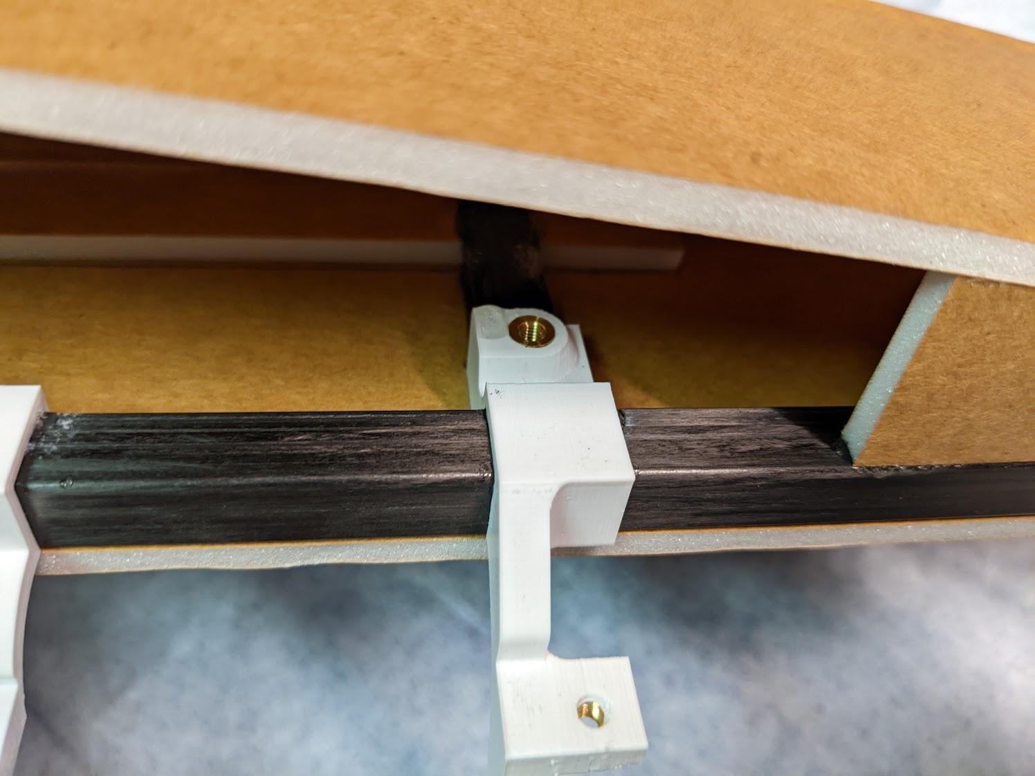
Install threaded inserts in the top of the forward and aft 3BSM mounts.
-
Install threaded inserts in the underside of the aft 3BSM mount, used for capturing the rear wing bolts.
-
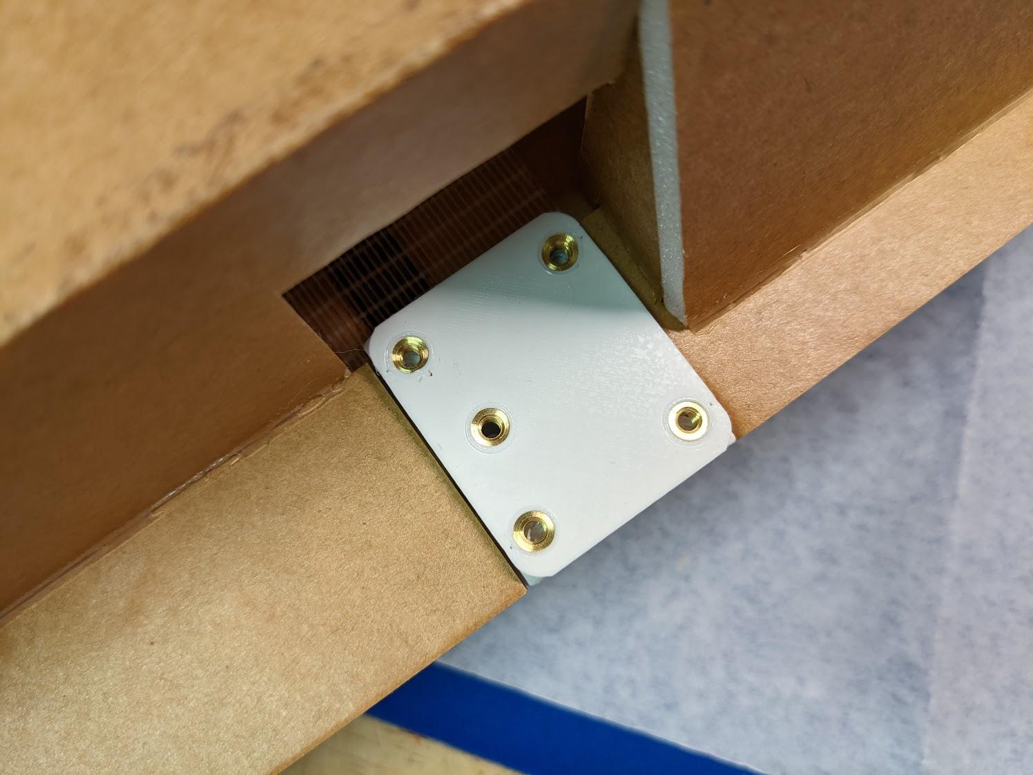
Install five threaded inserts in each main gear mount.
Nose assembly
-
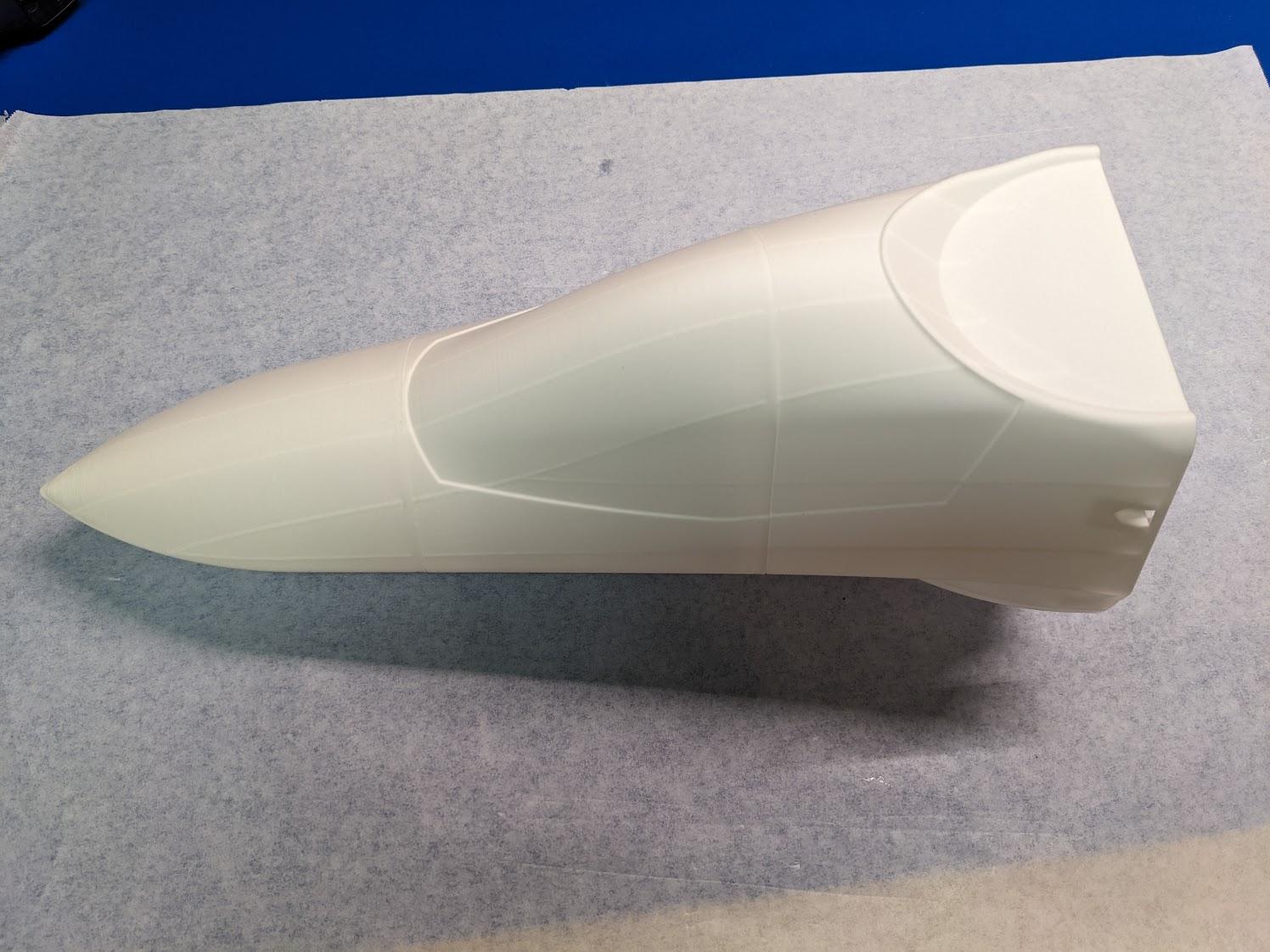
Glue the three nose sections together as shown.
-
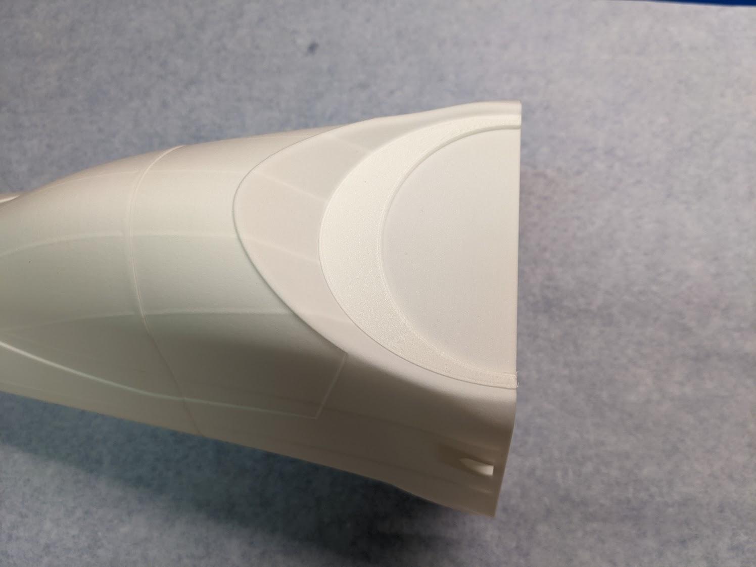
Glue the upper fan doubler to the aft section of the nose assembly.
-
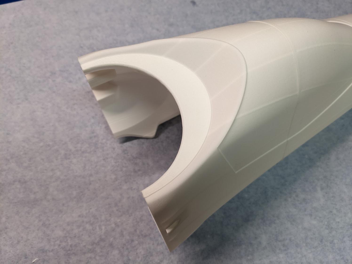
Cut out the circular fan mounting area.
-
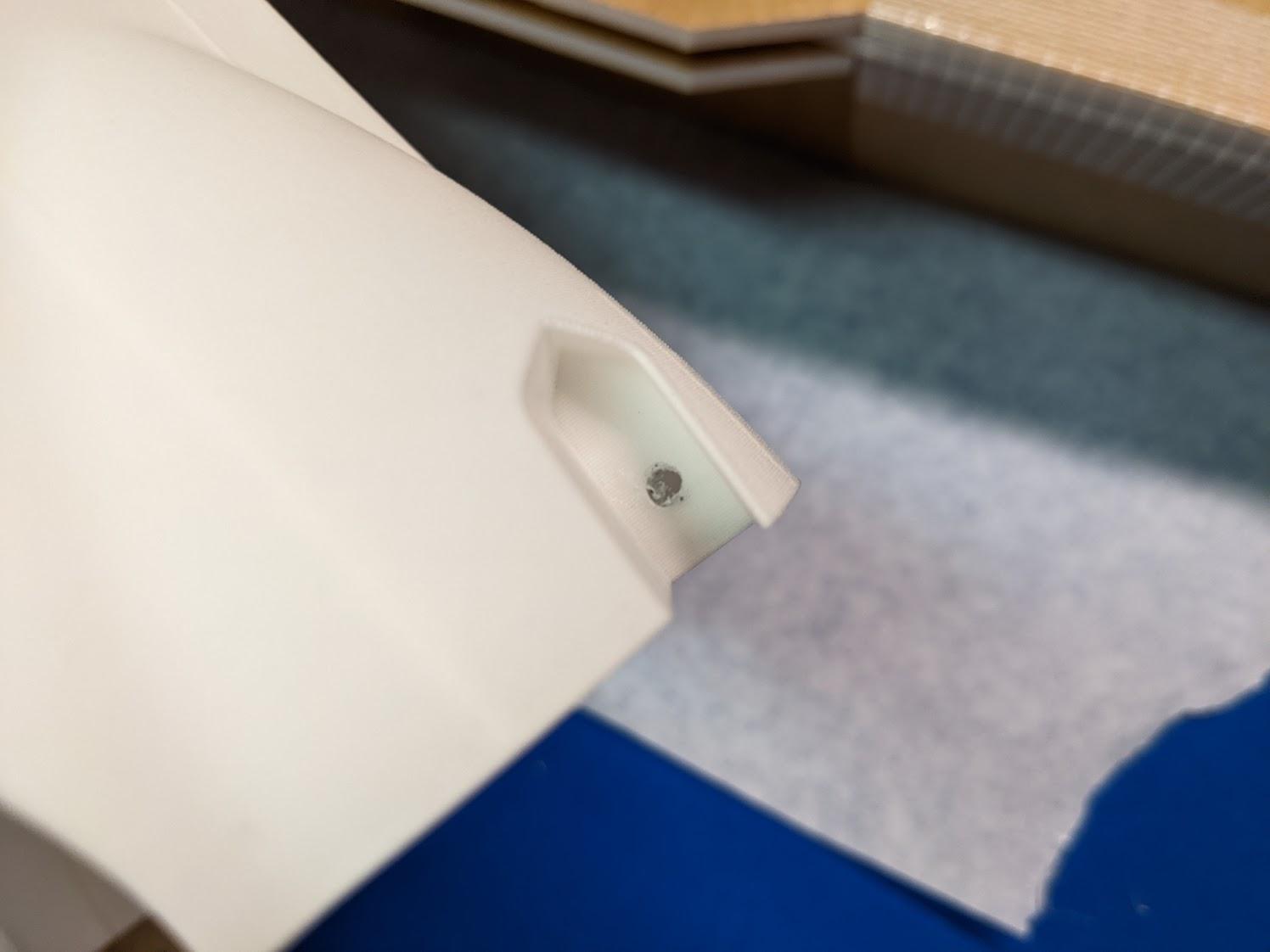
Drill clearance holes for the upper and lower nose mounting screws as shown.

-
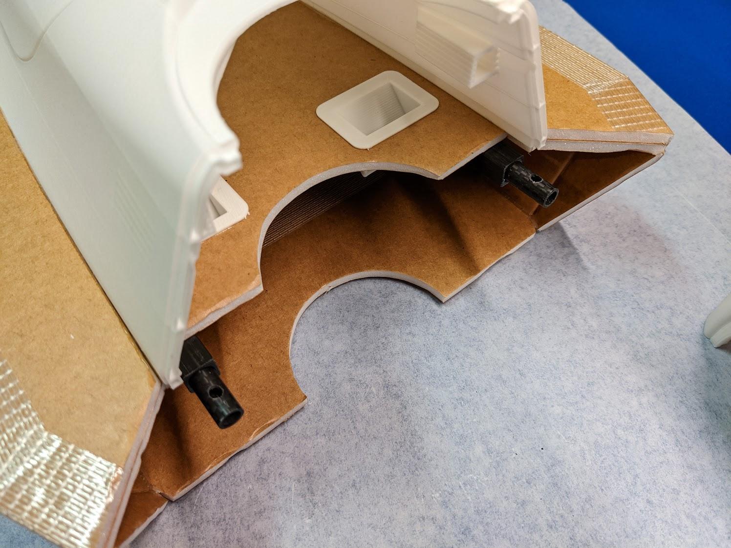
Cut two 55mm lengths of 8mm carbon tube. Drill M3 clearance holes centered 7.5mm from one end. Glue these tubes into the carbon square fuselage spars, protruding 15mm from the front.
-
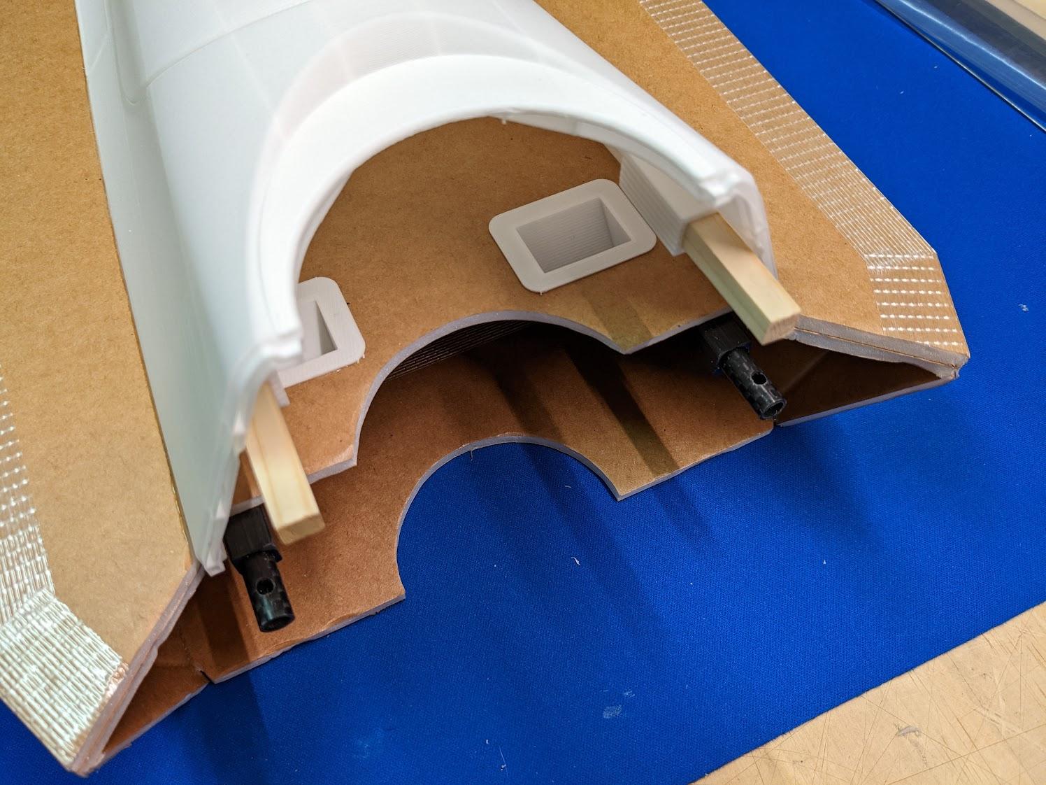
Cut two 55mm lengths of 5/16" (8mm) wood square dowel. Use CA to glue them into the upper fuselage.
-
Install six threaded inserts in the nose gear mount.
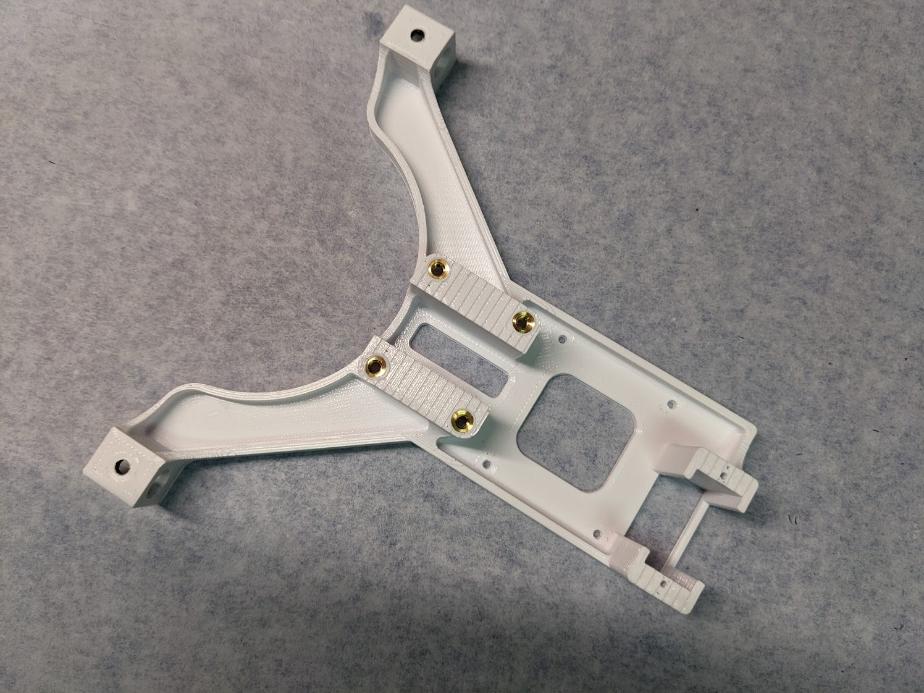
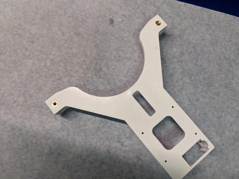
-
Install a threaded insert in each lift fan mount.
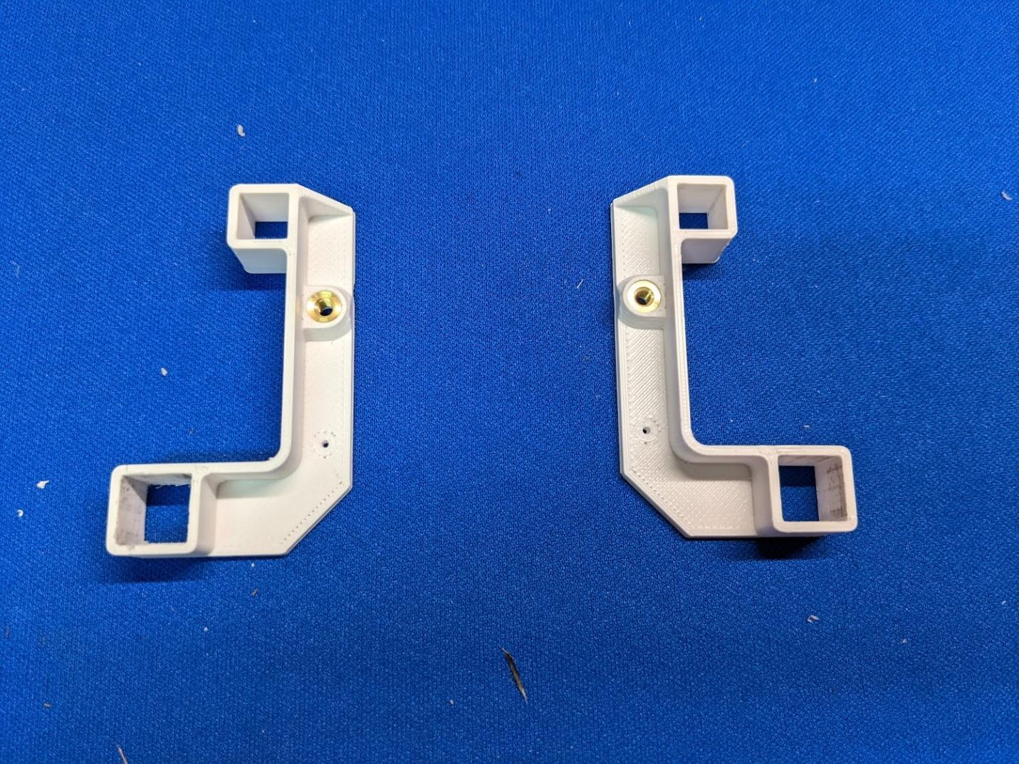
-
Slide the lift fan mounts over the square carbon fuselage spars and the square dowel joiners.
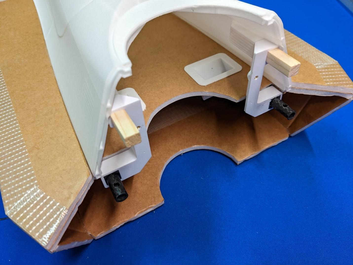
-
Slide the nose gear mount over the round carbon tube joiners in the nose. The holes in the tubes should align with the threaded inserts in the mount.
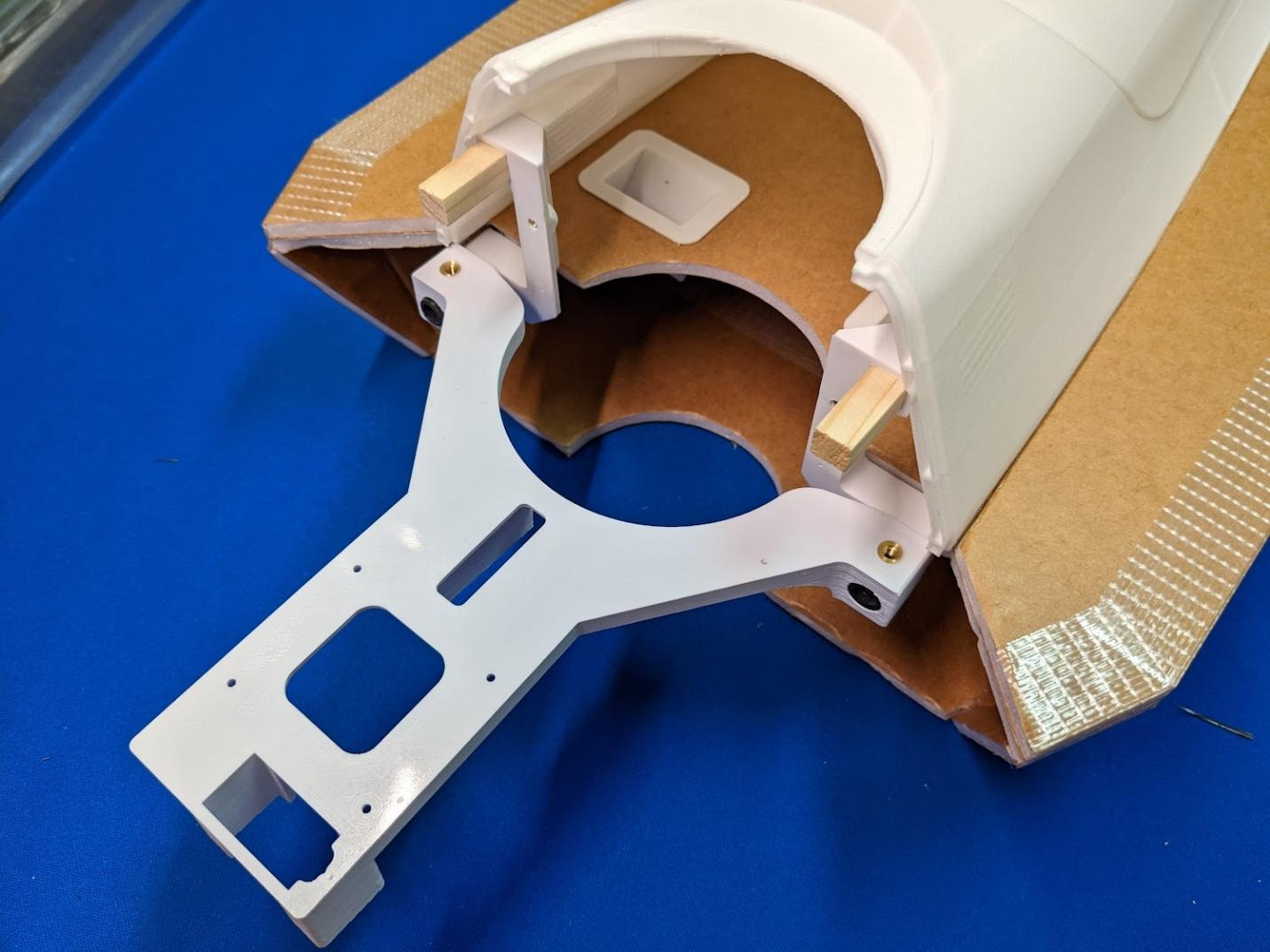
-
Slide the nose over the nose gear mount and onto the square wood joiners. Ensure that the aft edge of the nose properly interlocks with the forward edge of the upper fuselage.
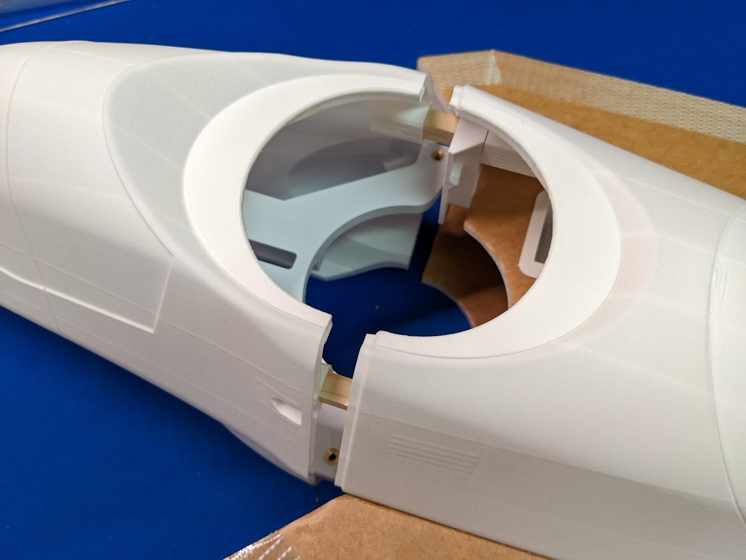
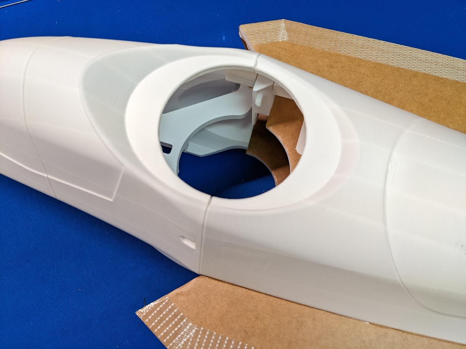
-
Use two M3 x 20mm cap screws to secure the underside of the nose. These screws should pass through the nose gear mount and carbon tube joiners and engage the threaded insert on the opposite side.
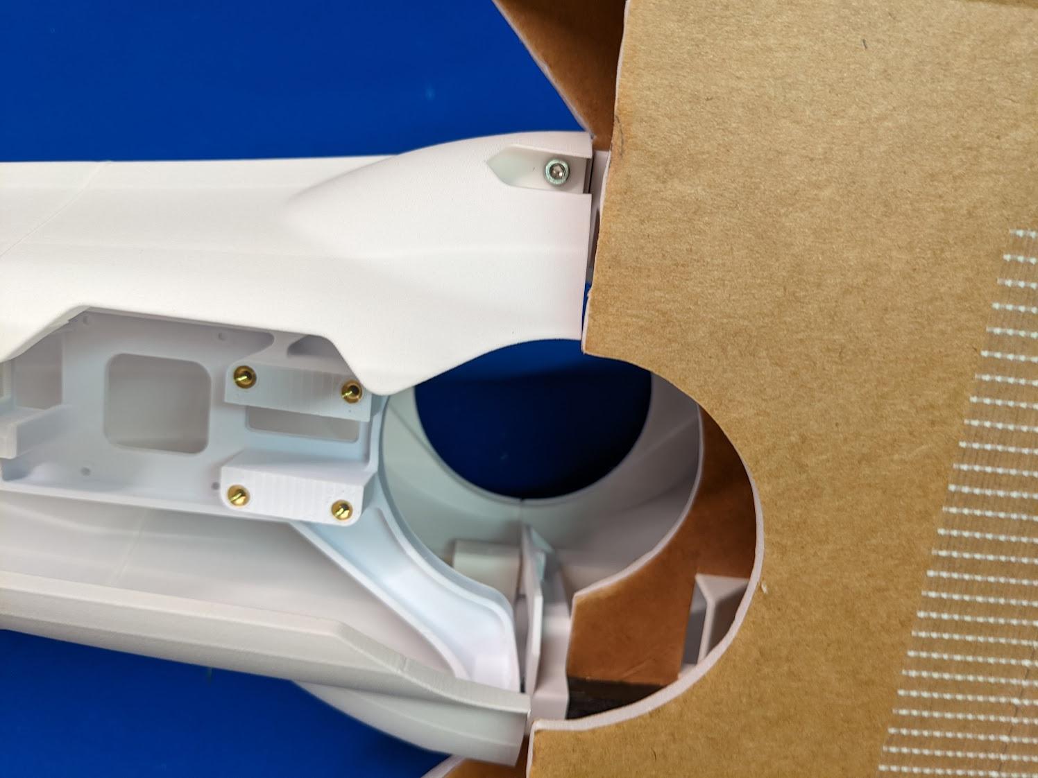
-
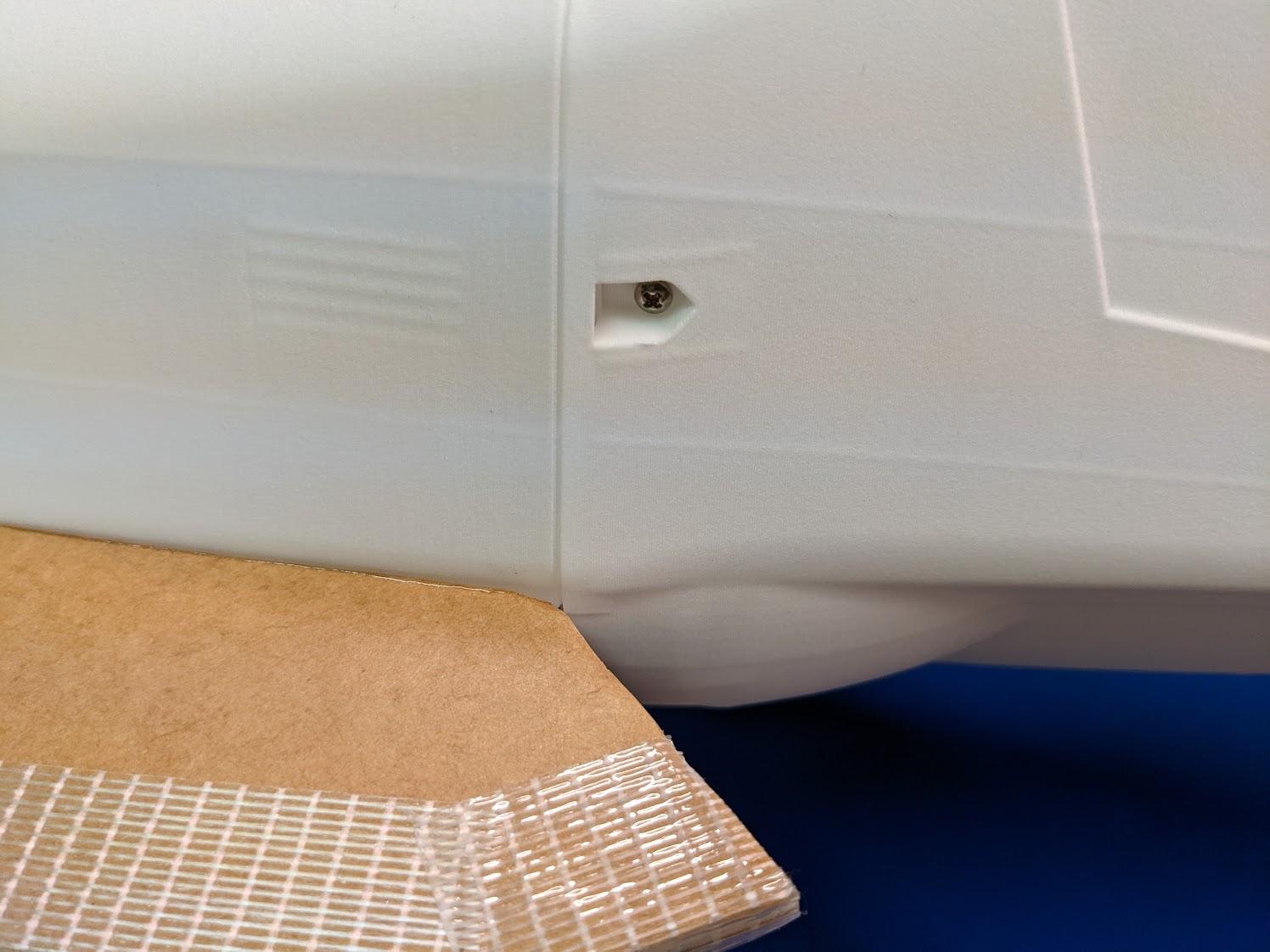
Use two #2 x 5/16" self-tapping screws to secure the top of the nose to the wood square dowels.
Control surfaces and tail assembly
-
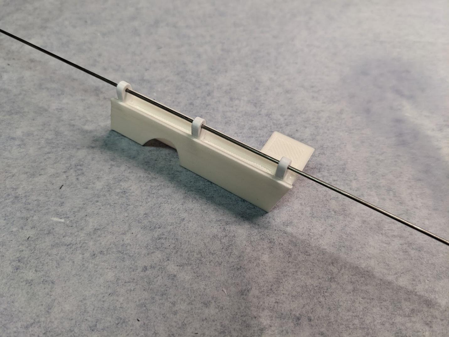
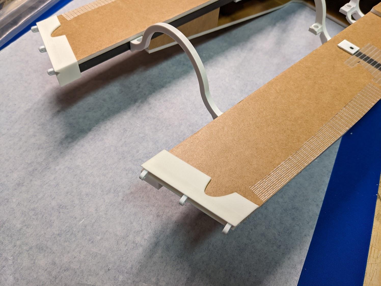
Use CA to install the stabilator hinge inserts into their pockets in the aft fuselage stiffeners. Use a section of pushrod to keep the hinge axis aligned while glue cures.
-
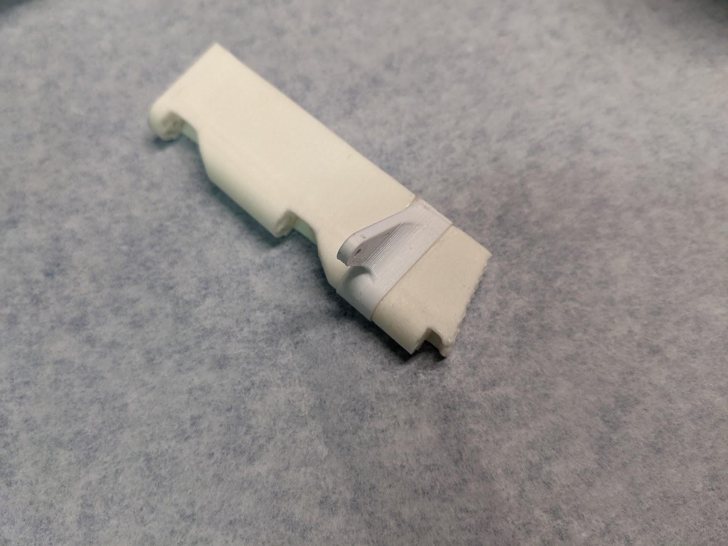
Use CA to attach the stabilator control horns to the stabilator stiffeners in the orientation shown.
-
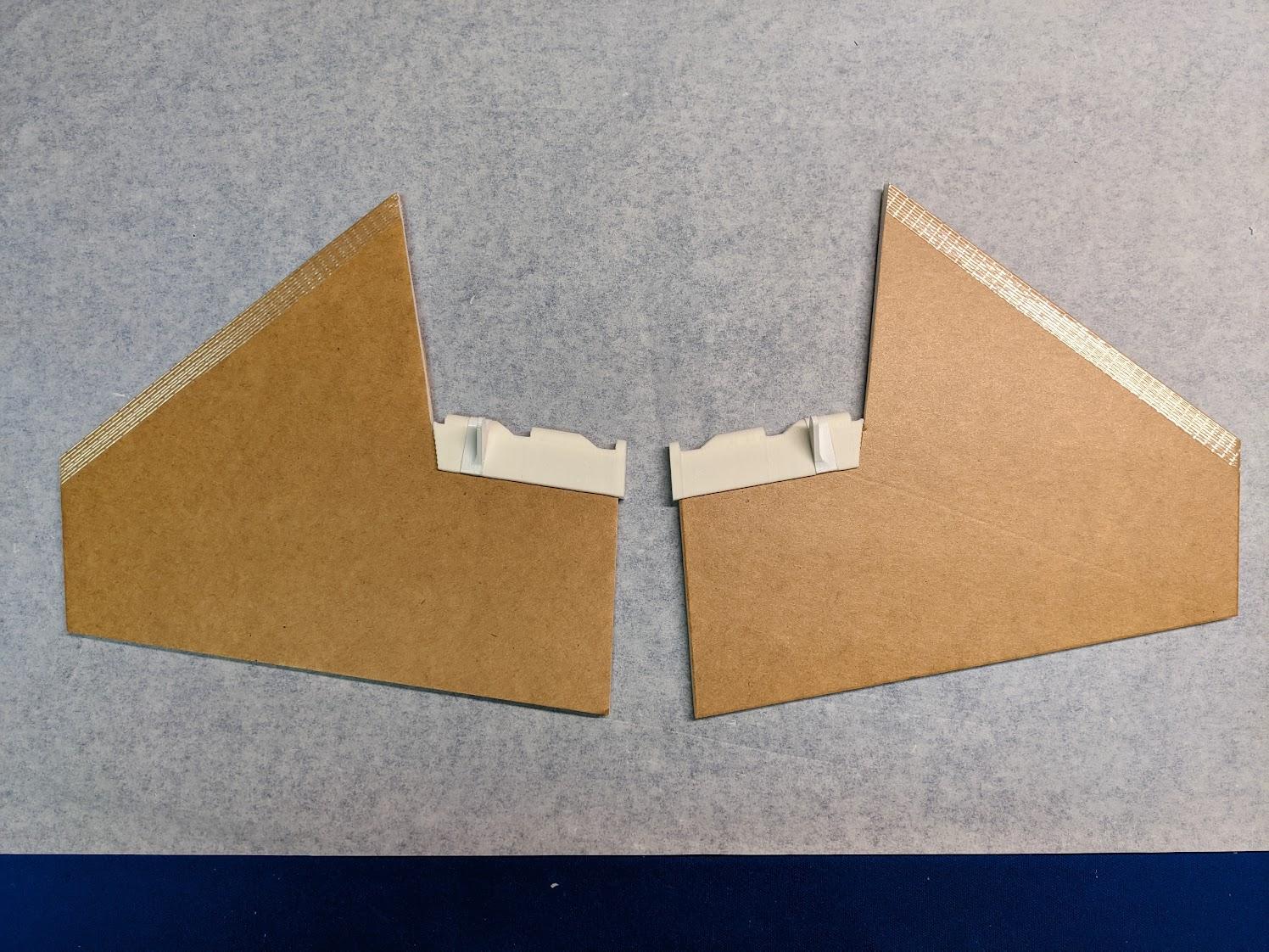
Use epoxy to join the stabilator stiffener and control horn assemblies to the foam stabilators. Wrap a thin piece of strapping tape around the leading edge of each stabilator.
-
Use epoxy to install the aft fuselage stiffeners over the foam and carbon fuselage components.
-
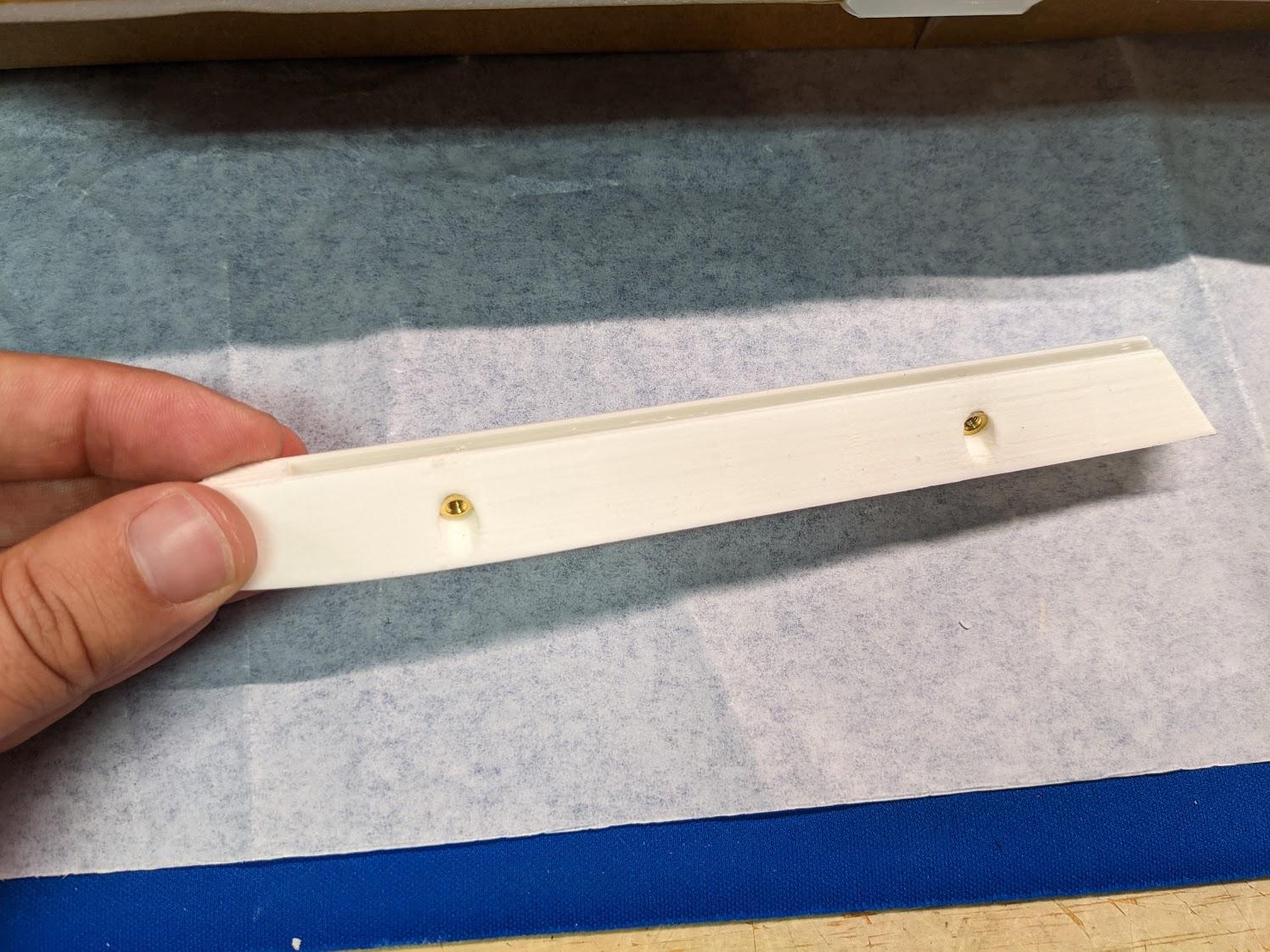
Install two threaded inserts in each vertical tail base.
-
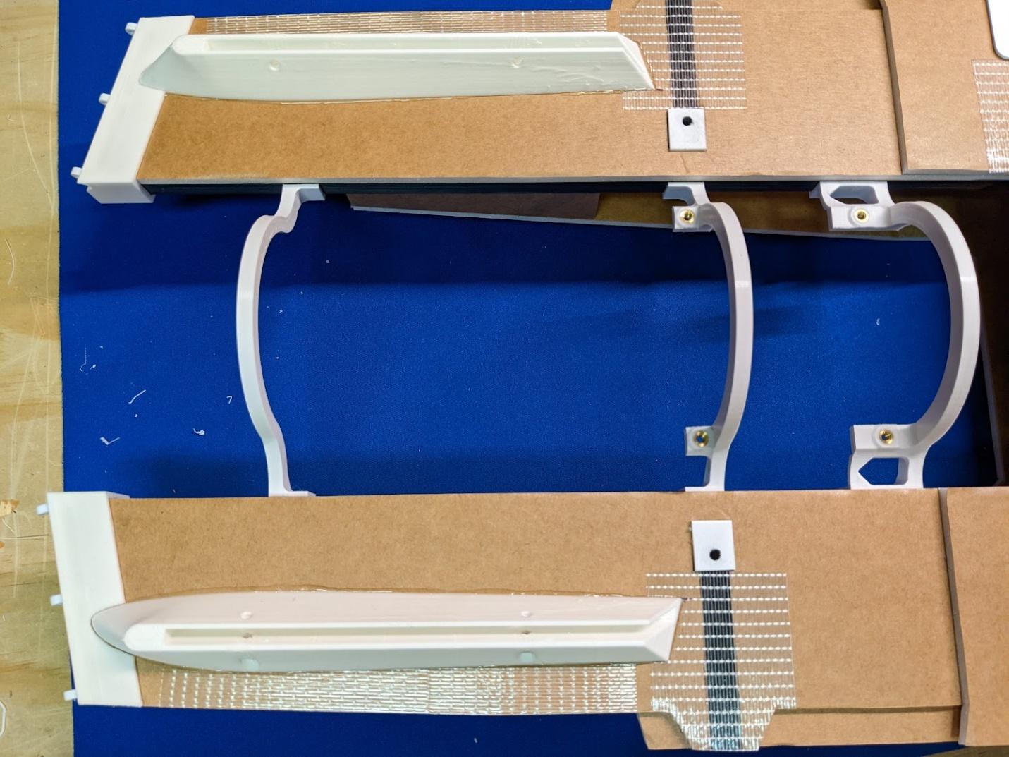
Use epoxy to mount the vertical tail bases to the aft fuselage. Ensure that they're parallel and aligned.
Battery hatch assembly
-
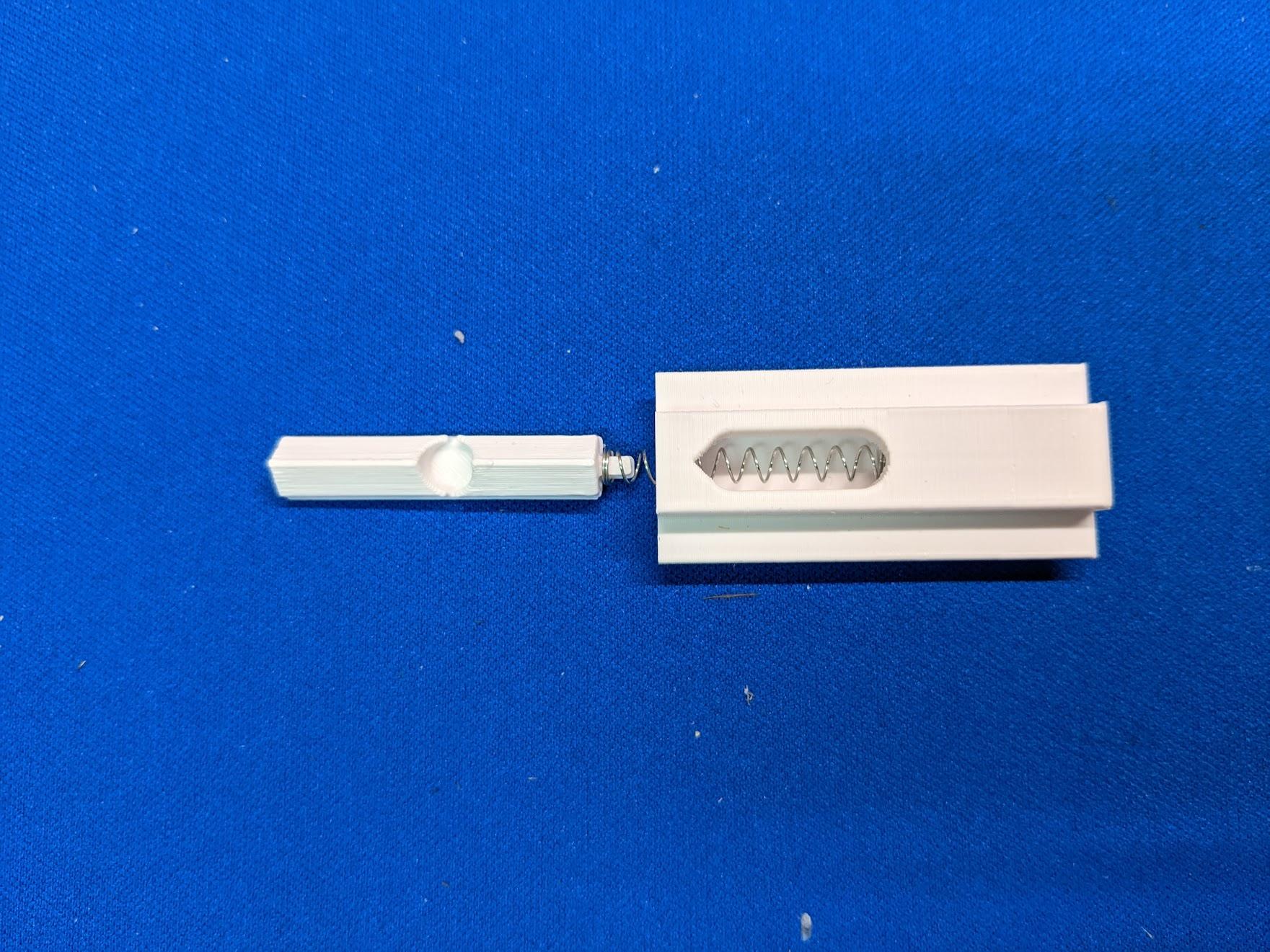
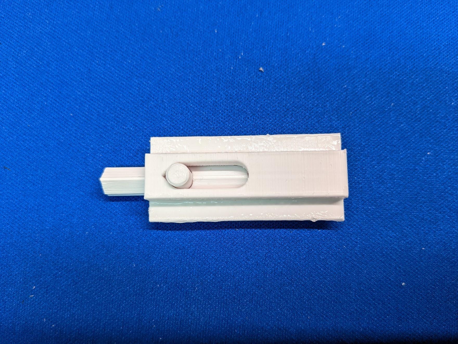
Slide the battery hatch latch into the holder along with a pen spring.
-
Glue the small round latch tab into place, securing the assembly.
-
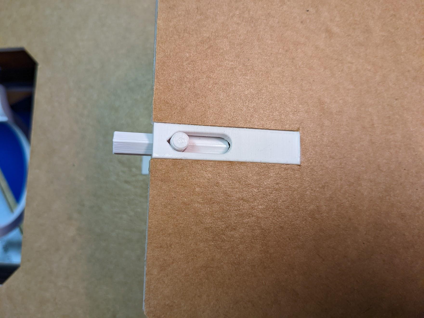
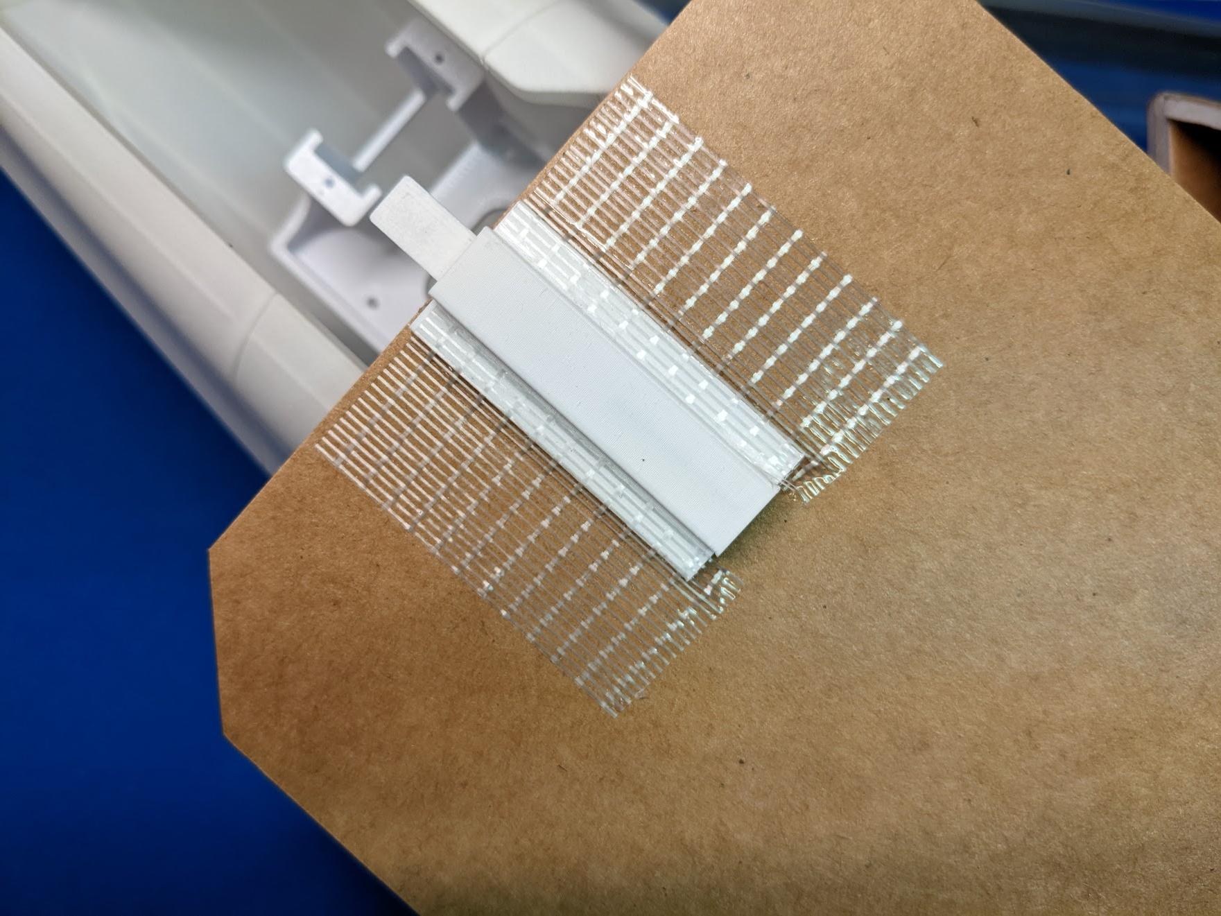
Glue the completed hatch latch assembly into the foam battery hatch panel and reinforce with tape.
-
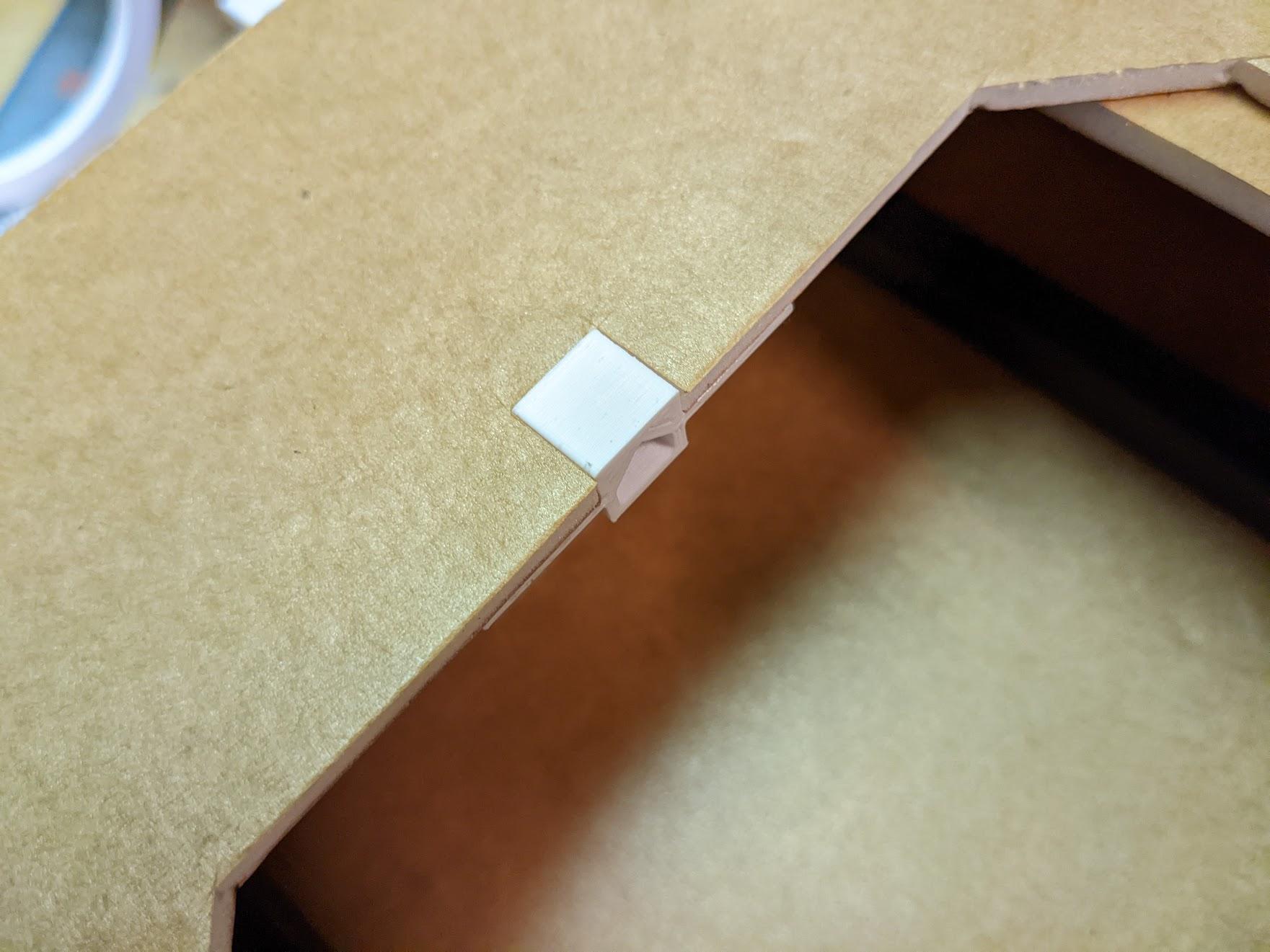
Glue the battery hatch latch receptacle into the cutout in the underside of the fuselage.
Finishing touches
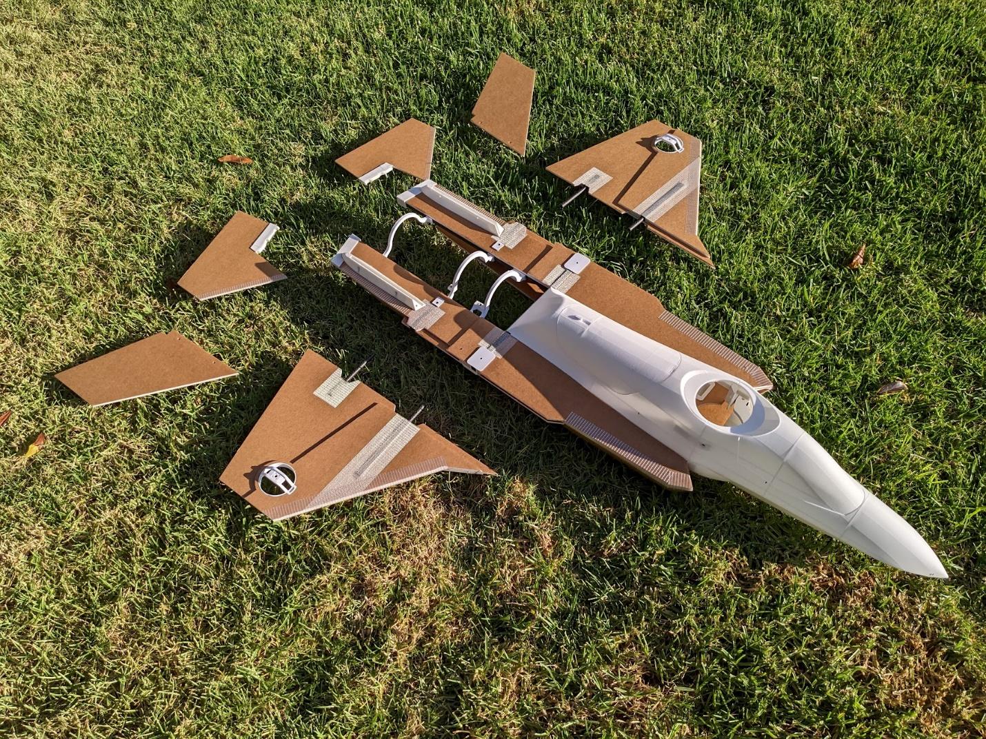
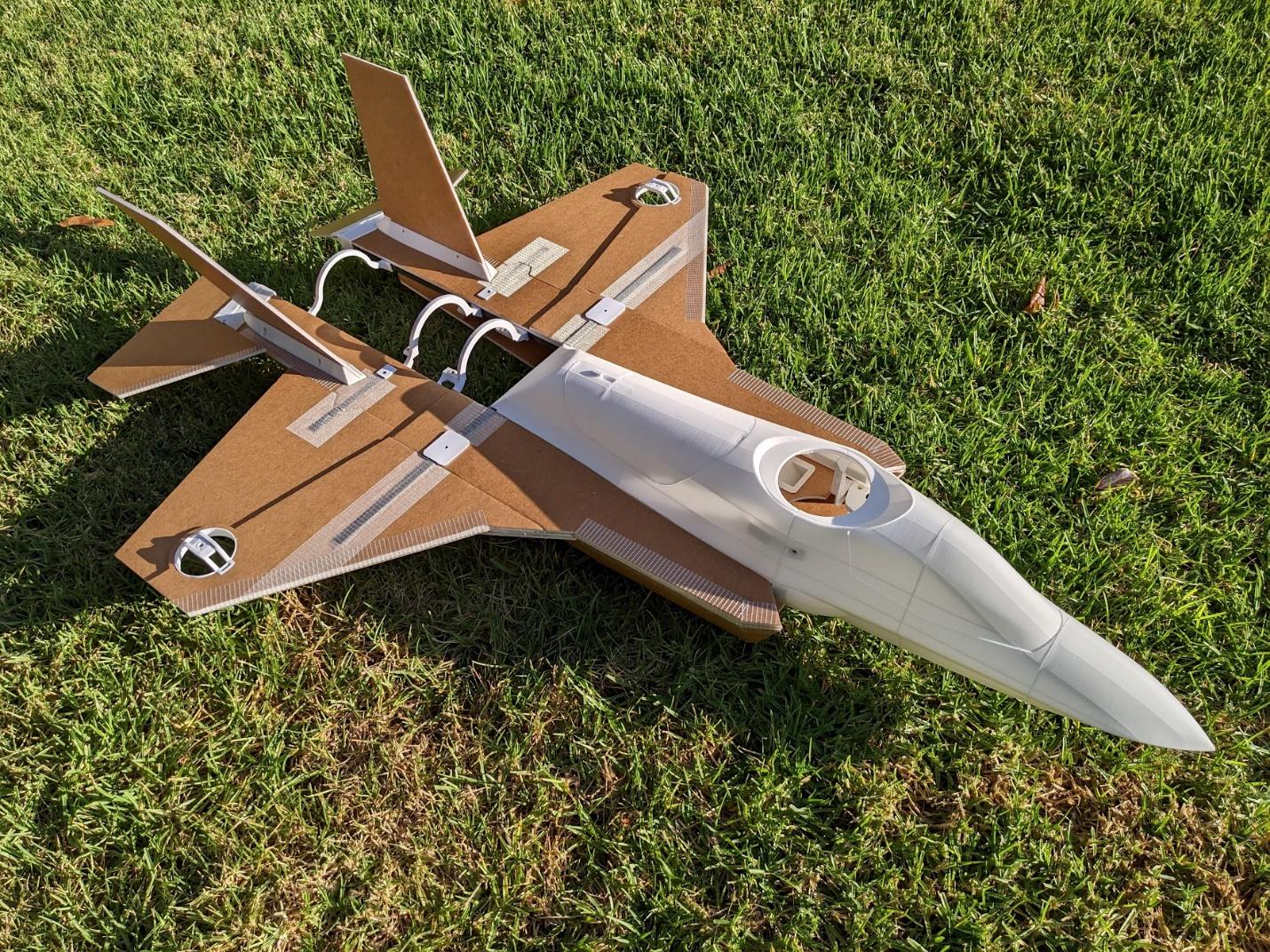
The wings slide into place and secure with four M3 x 20mm cap screws. The verticals secure with four M3 x 16mm cap screws – punch holes for these to pass through the foam. With the airframe complete, it's a great time to paint your model if desired.
Landing gear installation
-
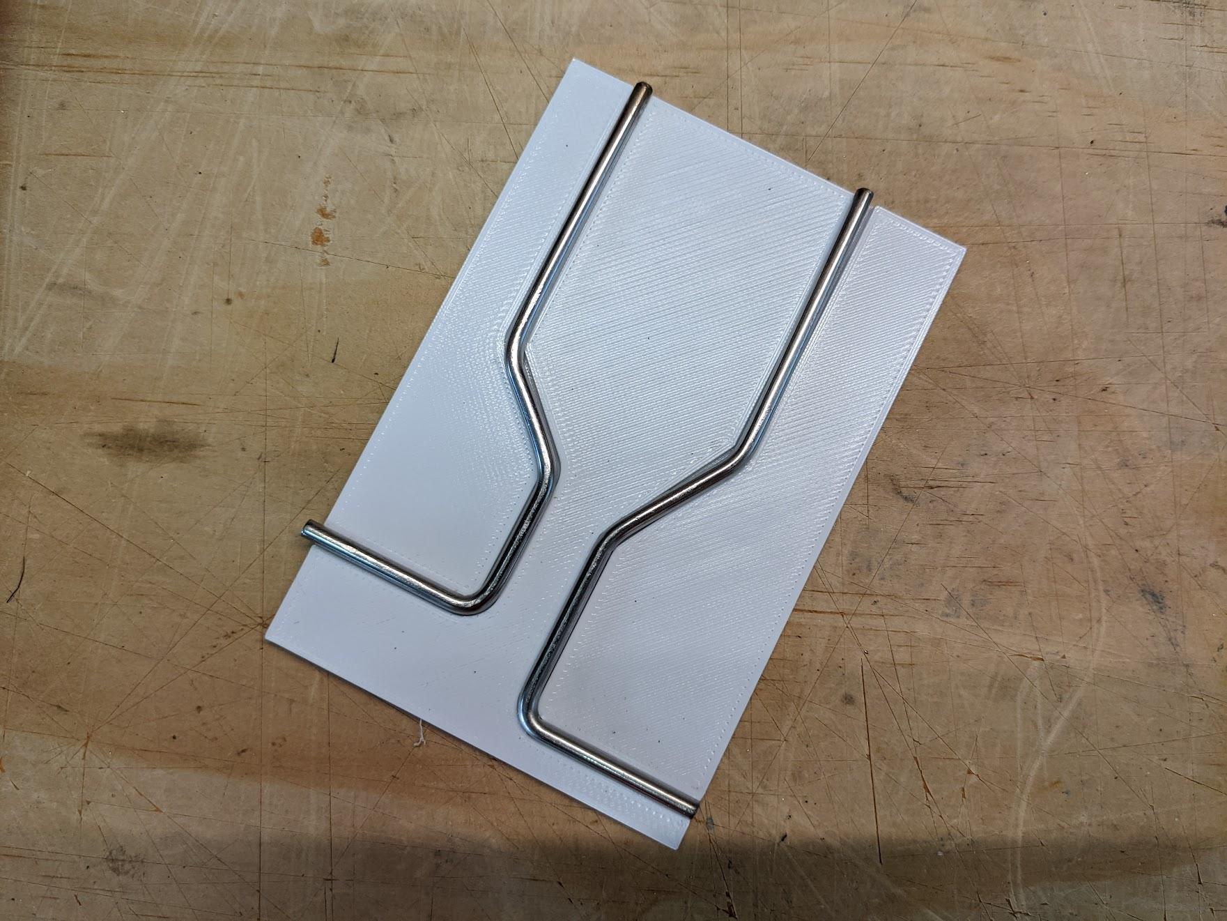
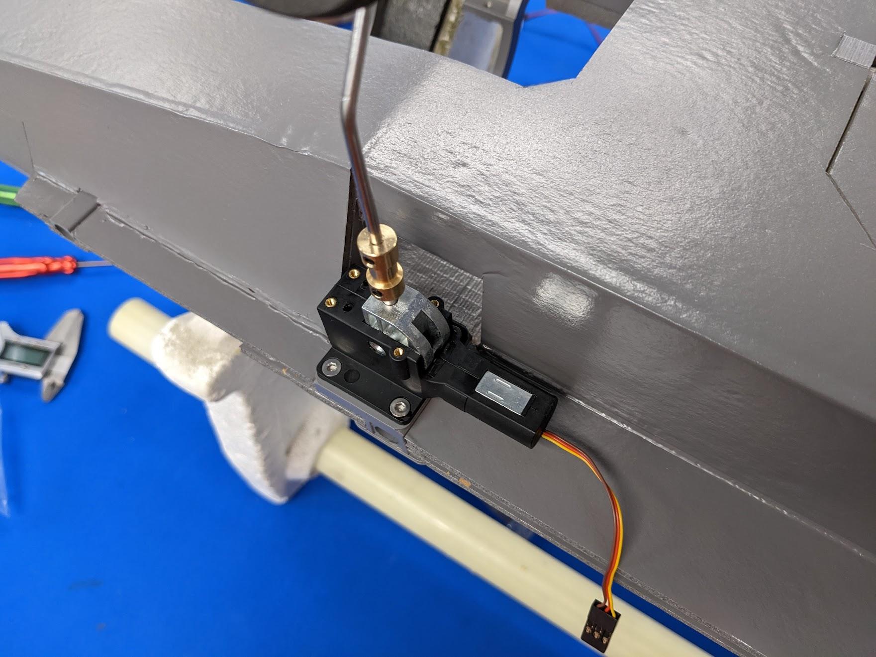
Use the printed guide to bend 3mm or 1/8" steel rod into the shape of the landing gear struts.
-
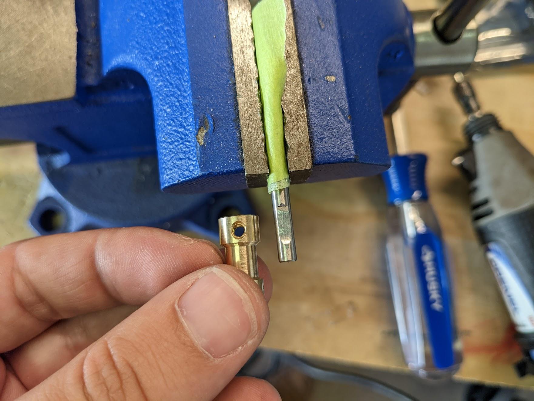
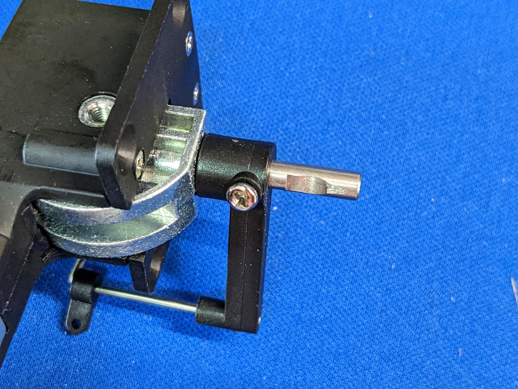
Grind flat spots to engage the set screws on the brass shaft couplers.
-
If necessary, extend the flat spots on the retract units to also accommodate the couplers.
-
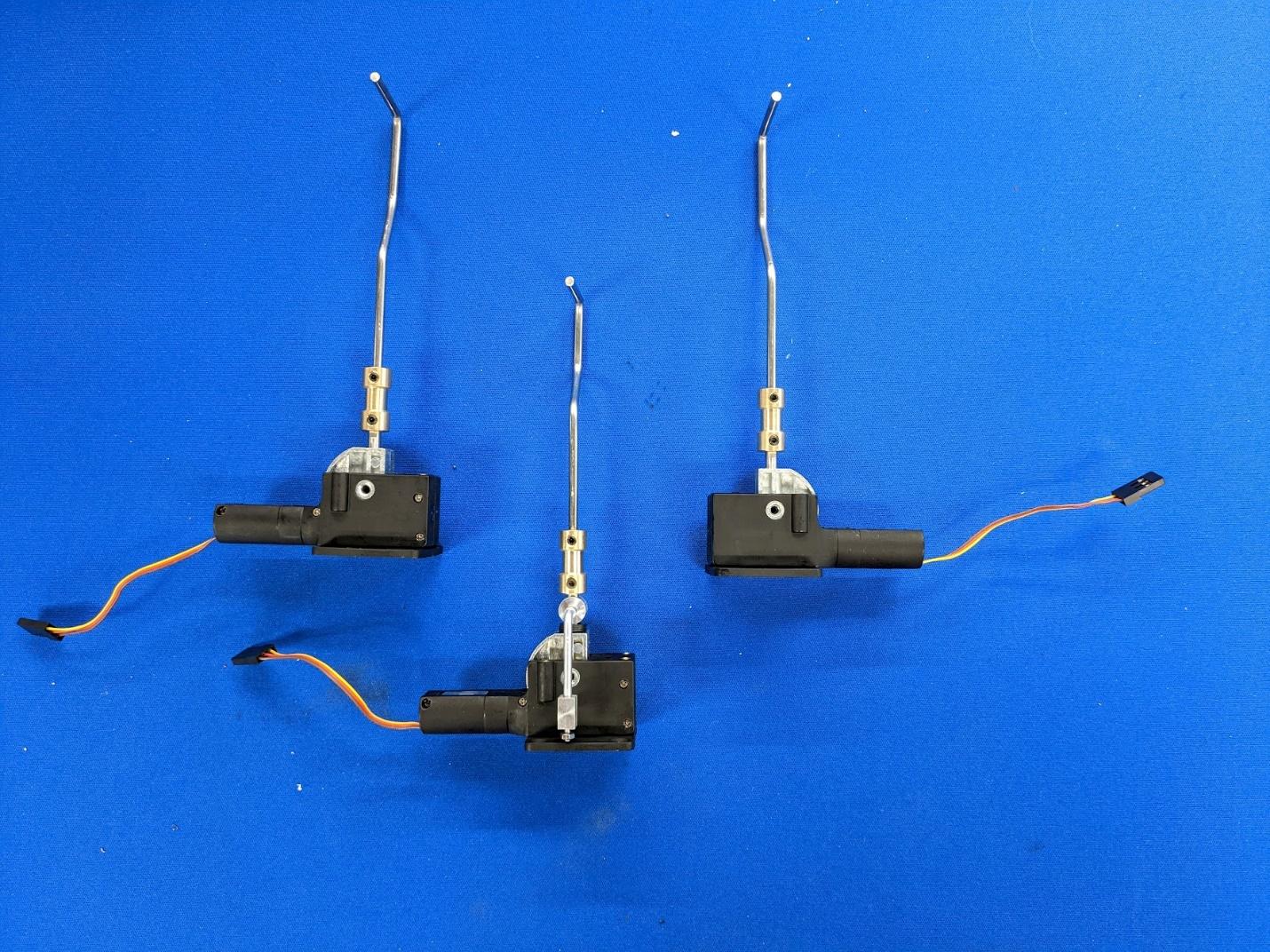
Use the couplers to install the steel struts onto the retract units.
-
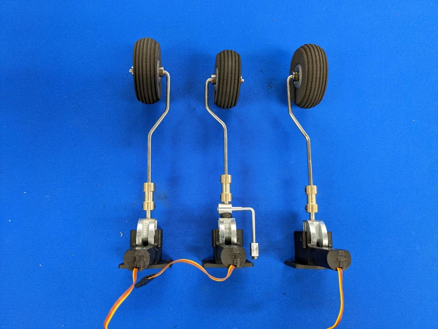
Install the wheels using 1/8" shaft collars on either side.
-
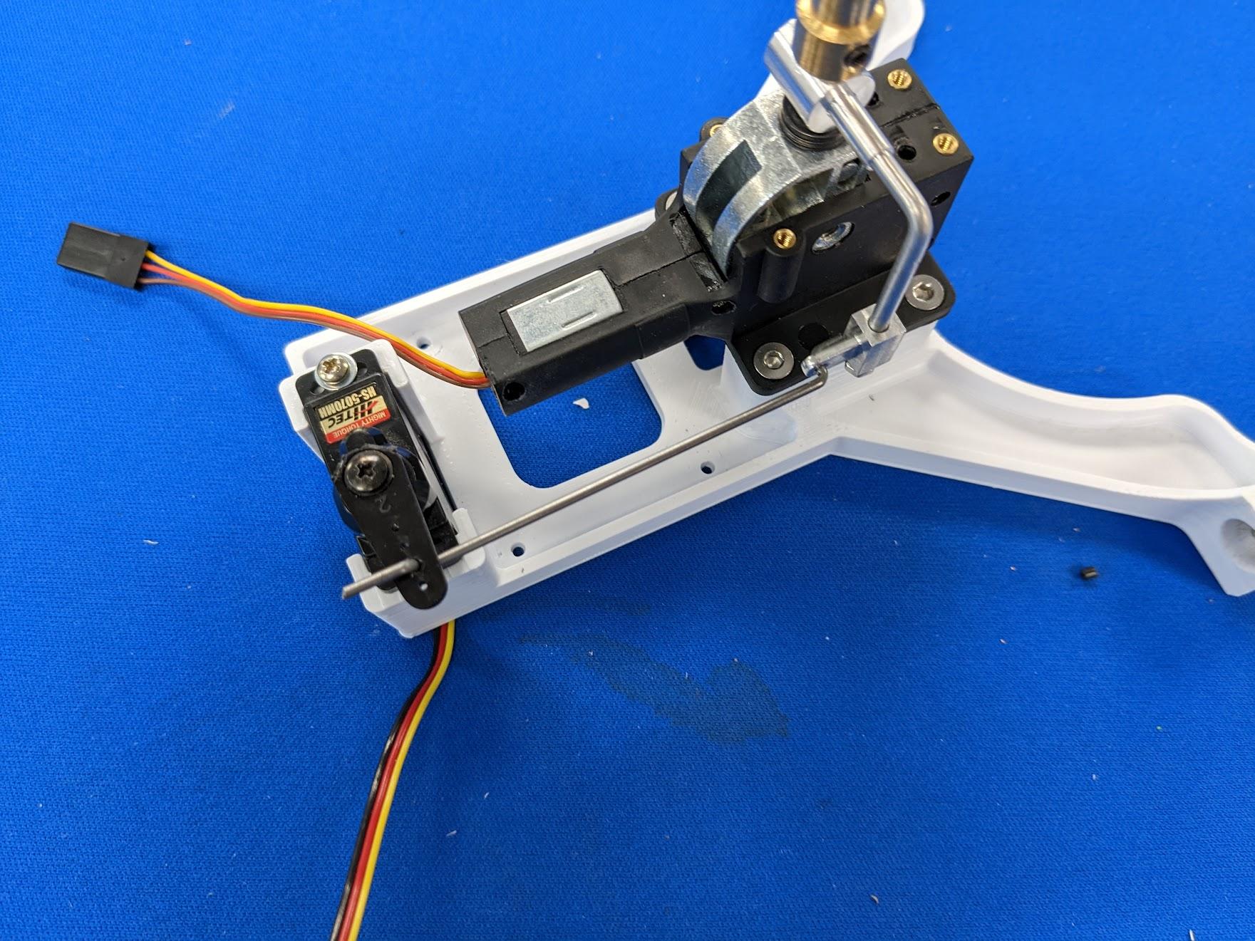
Mount the nose retract unit using four M3 x 6mm flat head screws. Install the nose steering servo with two #2 x 5/16" screws and washers plus a steel pushrod.
-
Mount the main retract units using four M3 x 6mm flat head screws each.
Power system installation
-
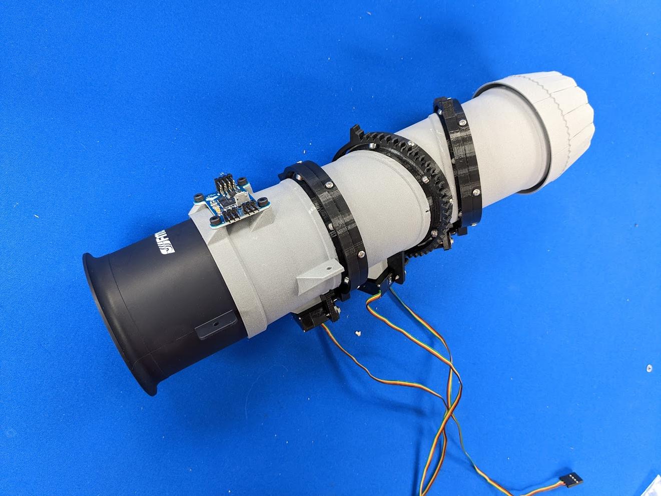
Follow the 3BSM video guide series to assemble the 3BSM. While the guide details assembly of the 90mm version, the 70mm version is nearly identical. There are just six screws/bearings per ring instead of eight.
-
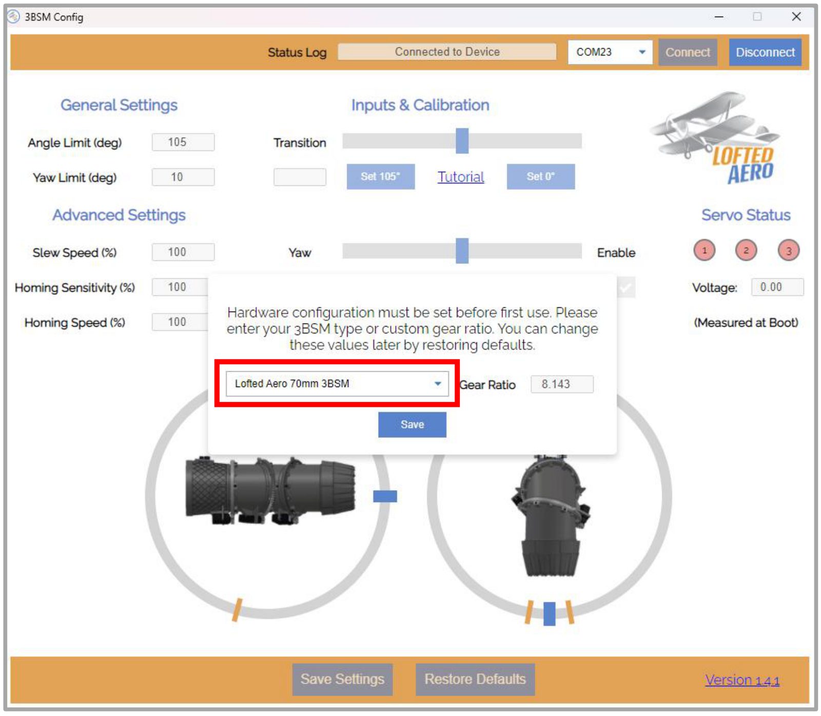
When using the 3BSM configuration app to set up the controller board, be sure to select the defaults for the 70mm size 3BSM when prompted. This sets the gear ratio and homing parameters appropriately.
-
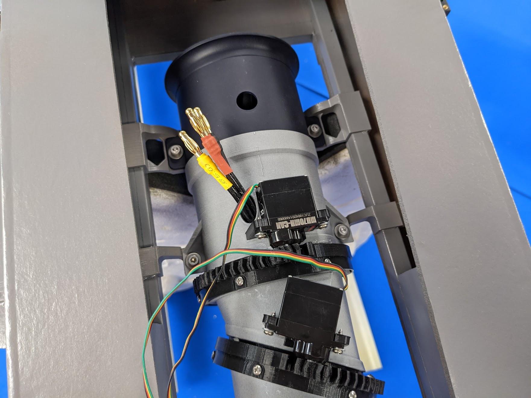
Use four M3 x 10mm socket head screws and washers to mount the completed 3BSM and the fan onto its mounts.
-
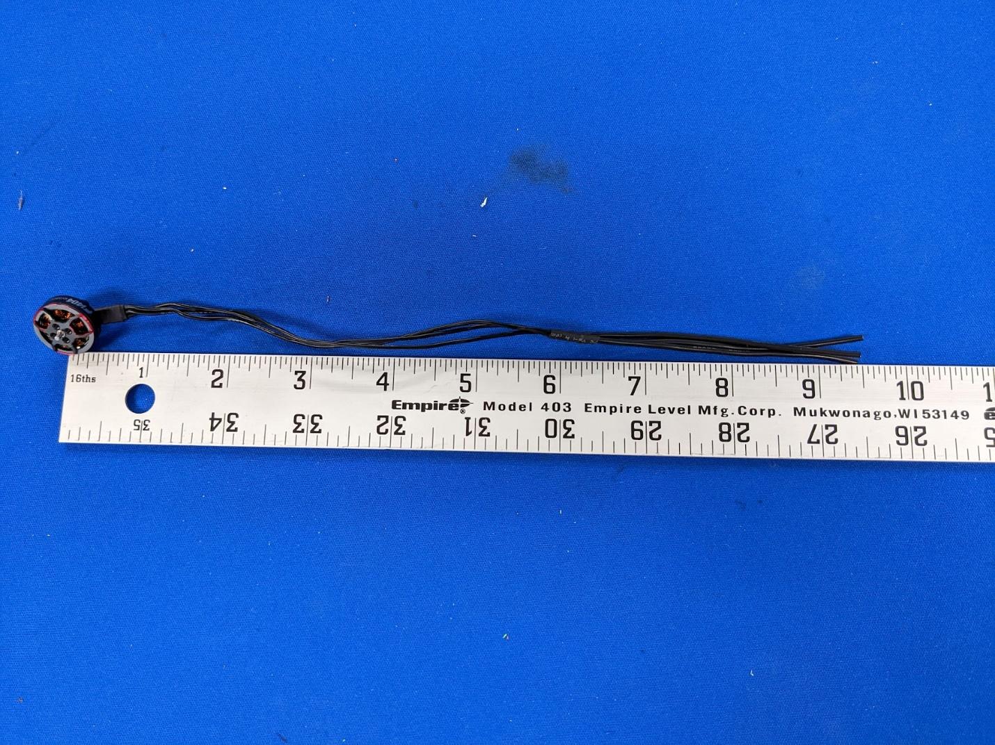
Extend the wires on the roll thruster motors as shown.
-
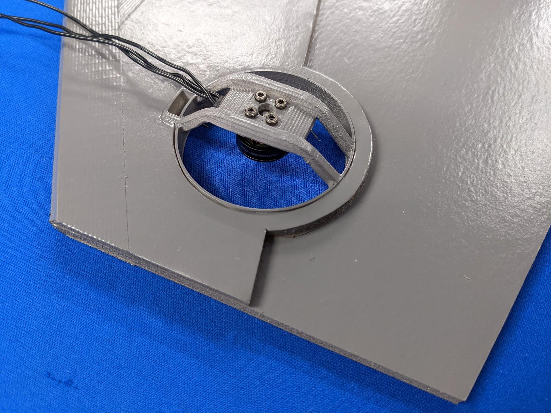
Use some of the screws included with the roll motors to mount them to the roll thruster housings.
-
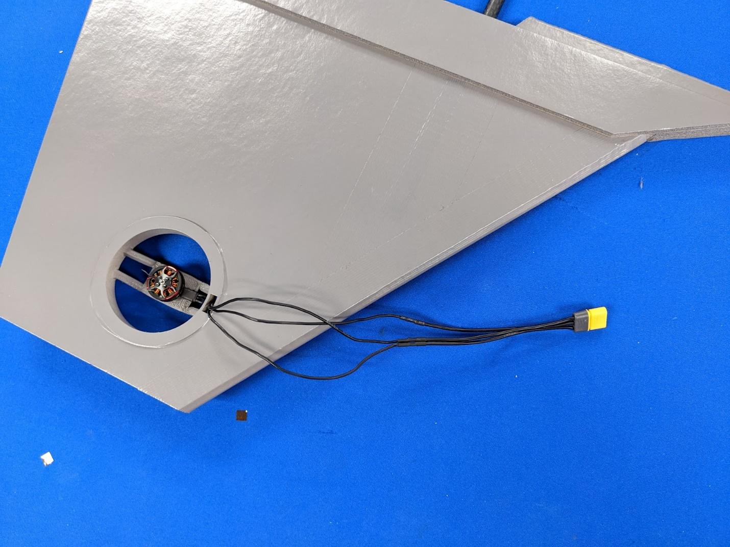
Pass the roll thruster motor wires through the mounts and install an MR30 connector on each.
-
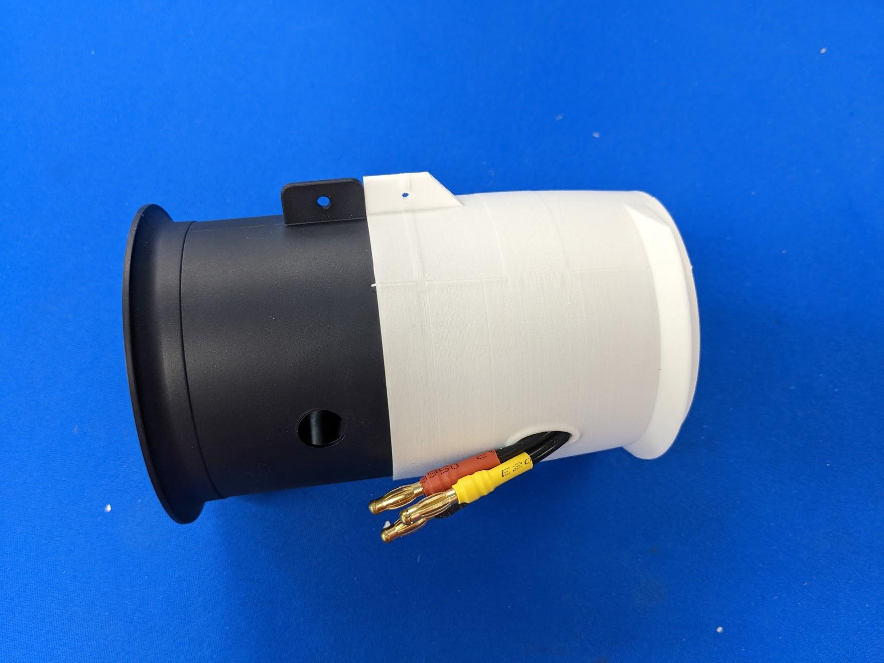
Slide the lift fan exhaust duct onto the aft edge of the lift fan. The "shelf" on the bottom of the duct should face aft.
-
Remove the nose and nose gear mount. Attach the lift fan to its mounts with two M3 x 10mm socket head screws and washers. Also use two self-tapping screws to secure the exhaust duct to the lift fan mounts.
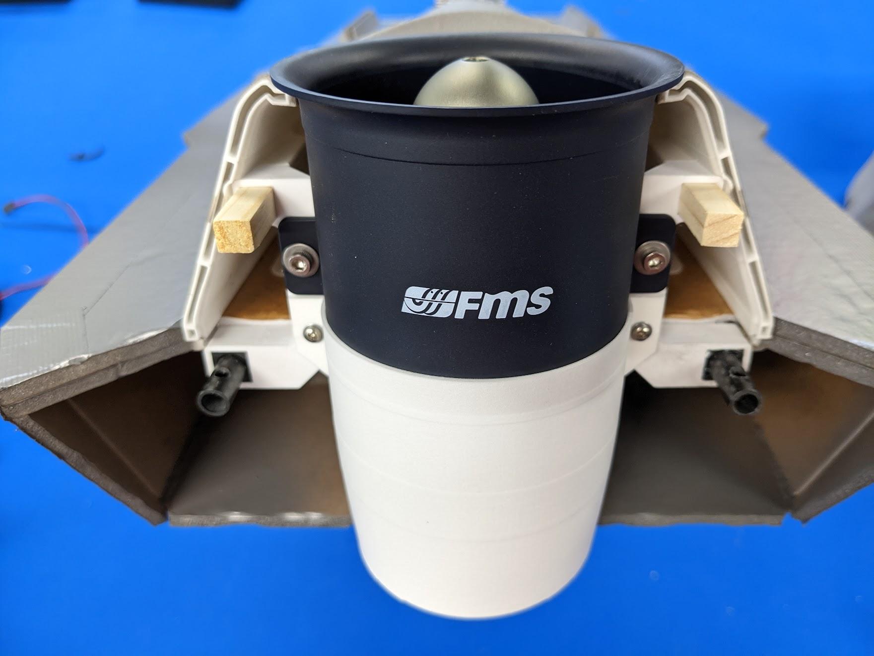
Servo installation
-
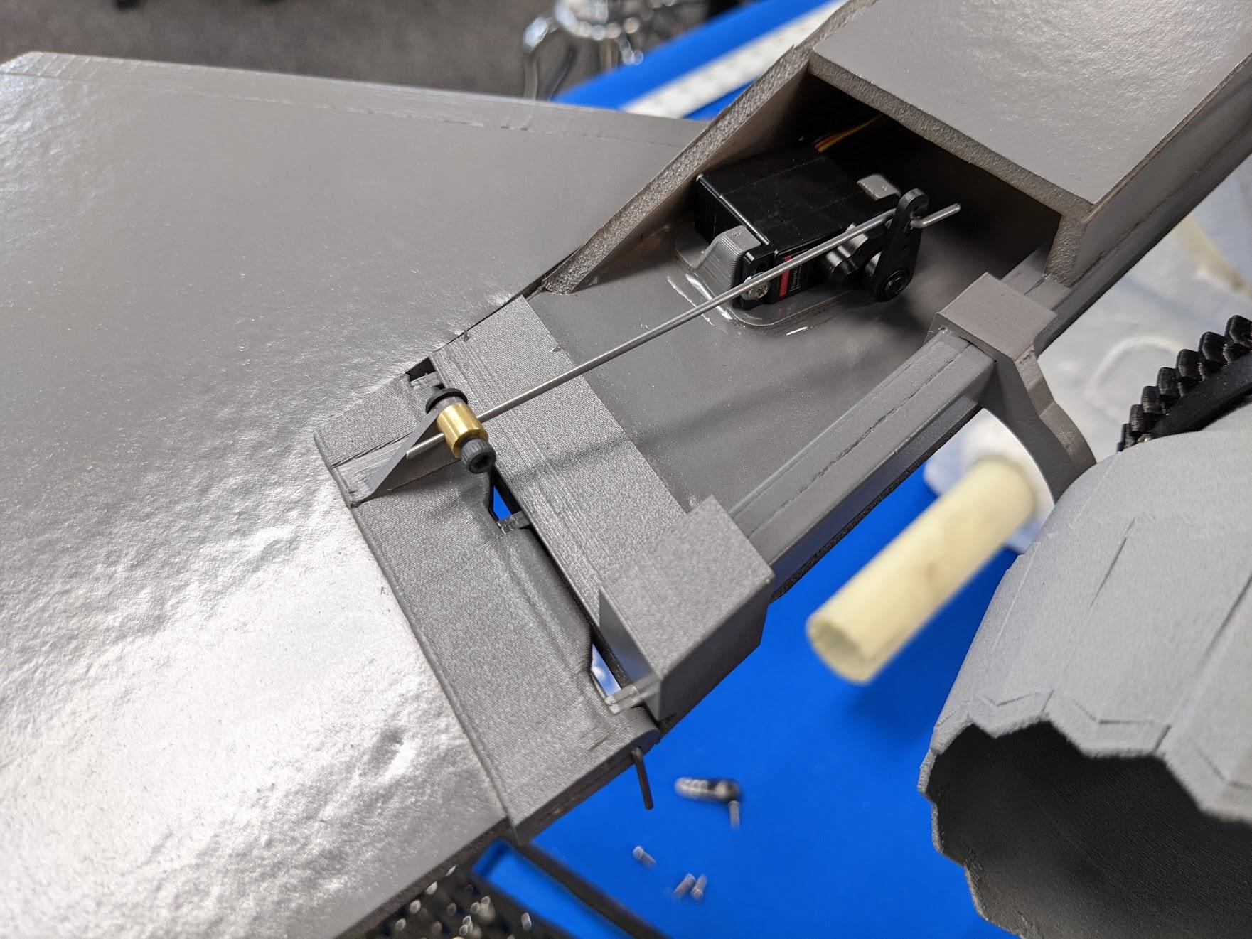
Use #2 x 5/16" self-tapping screws and washers to attach each stabilator servo to its mount plate. Center and install the servo arms.
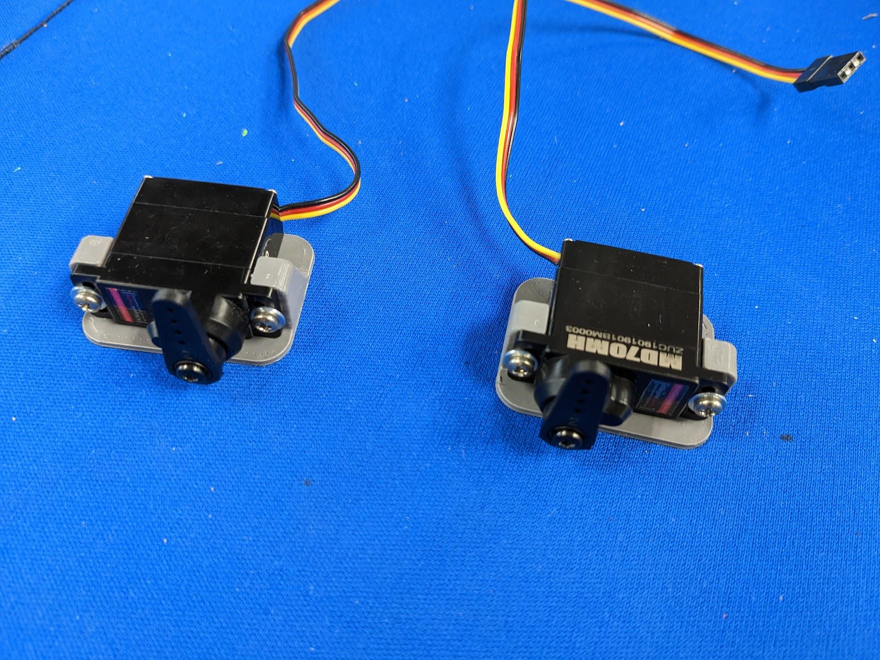
-
Scuff or remove the paint in the areas where the servo mount plates will attach. Scoring the paper covering the foam helps as well.
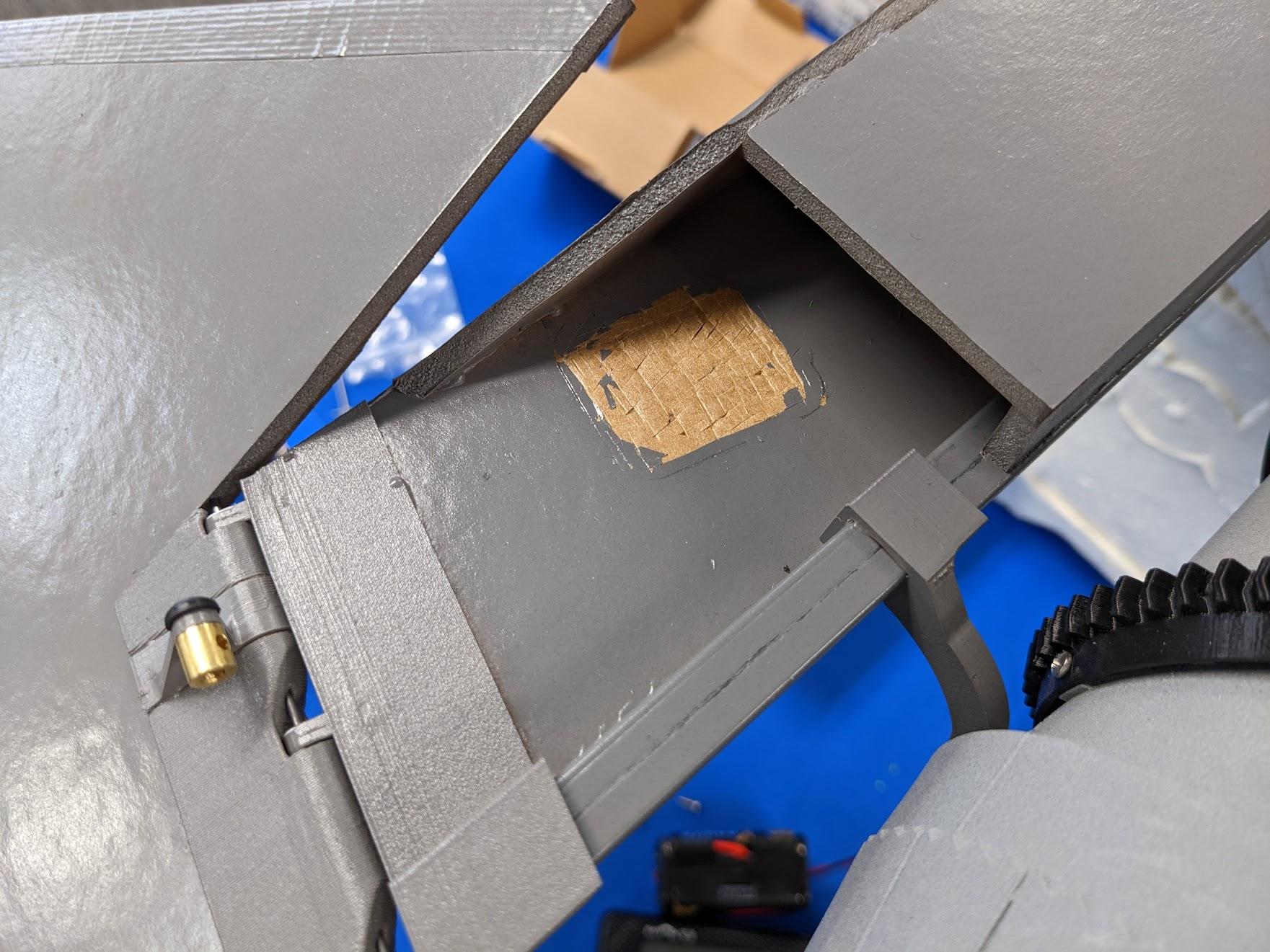
-
Use epoxy to glue the servo and mount plate assemblies in the location shown.
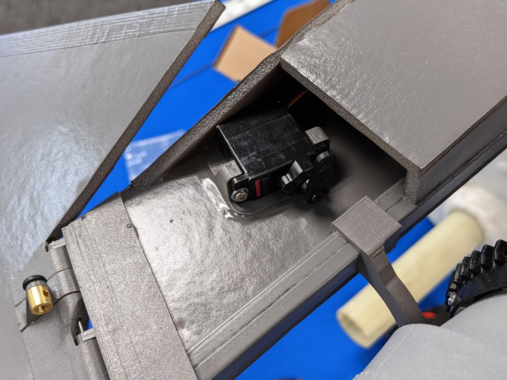
-
Connect the stabilators with pushrods and EZ-Connectors as shown.
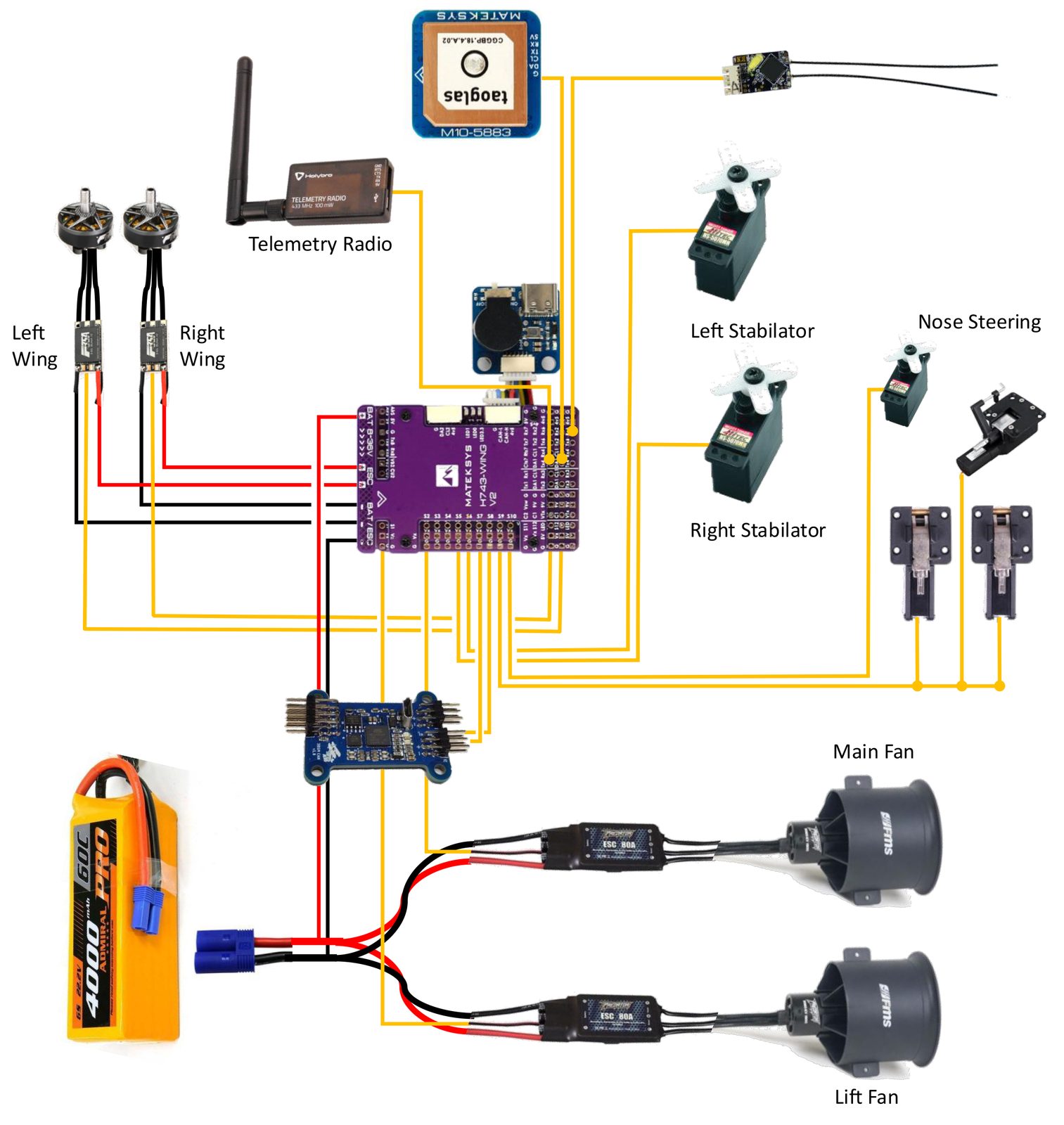
Avionics layout – Matek H743-Wing
This diagram details the avionics layout using the Matek H743-Wing and M10Q GNSS. The wiring configuration is the same for the TBS Lucid H7 Wing option as well.
Ports and functions – Matek H743-Wing or TBS Lucid H7 Wing
The recommended configuration uses the ports and connection scheme detailed below. If you wish to change sensors or output assignments, refer to the ArduPilot wiki to ensure that parameters are updated accordingly. The firmware flashing process is different – here's a useful video guide: Installing ArduPilot on an H743 Flight Controller.
Servos and motors
| Device | Autopilot Port |
|---|---|
| Lift Fan ESC | S1 (SERVO1) |
| Main Fan ESC | S2 (SERVO2) |
| Right Stabilator Servo | S5 (SERVO5) |
| Left Stabilator Servo | S6 (SERVO6) |
| 3BSM Controller Yaw | S7 (SERVO7) |
| 3BSM Controller Tilt | S8 (SERVO8) |
| Electric Retracts | S9 (SERVO9) |
| Nose Steering Servo | S10 (SERVO10) |
| Right Roll ESC | S11 (SERVO11) |
| Left Roll ESC | S12 (SERVO12) |
Sensors and peripherals
| Device | Autopilot Port |
|---|---|
| R/C Receiver | RX6 (if using PPM or S.BUS), TX6 (if using SRXL/DSM) |
| GPS/GNSS | CAN1 (if using CAN), TX2 RX2 DA1 CL1 (if using Serial + I2C) |
| Telemetry Radio | RX7 TX7 RTS7 CTS7 |
Power
| Device | Input | Output |
|---|---|---|
| BAT 8-36V Pads on H743 | 6S from main batteries | None |
| H743 Servo Power (Vx) | Set to 7.2V by soldering jumper pad. Refer to Matek documentation. | — |
Note
- Requires all servos to be HV capable!
- Do not connect ESC BEC (red wire) to H743, since it has a built-in regulator to power the servos.
- Power main ESCs direct from battery, not from BAT/ESC pads. The current draw is too high for the H743.
7.2V servo power and 5V power harnesses
-
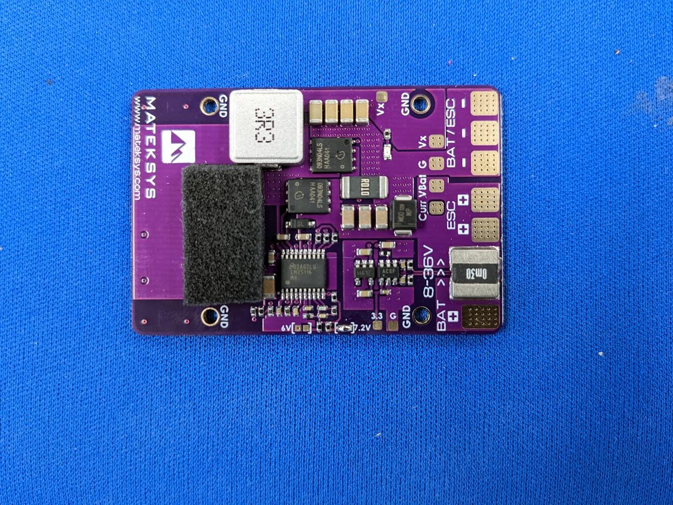
Solder the 7.2V jumper on the H743-Wing. This will provide 7.2V to the "Vx" rail, allowing for faster servo responses that particularly benefit 3BSM performance.
-
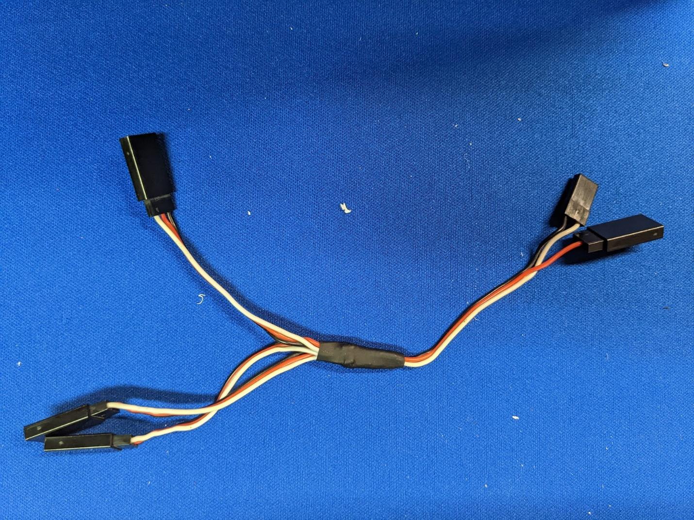
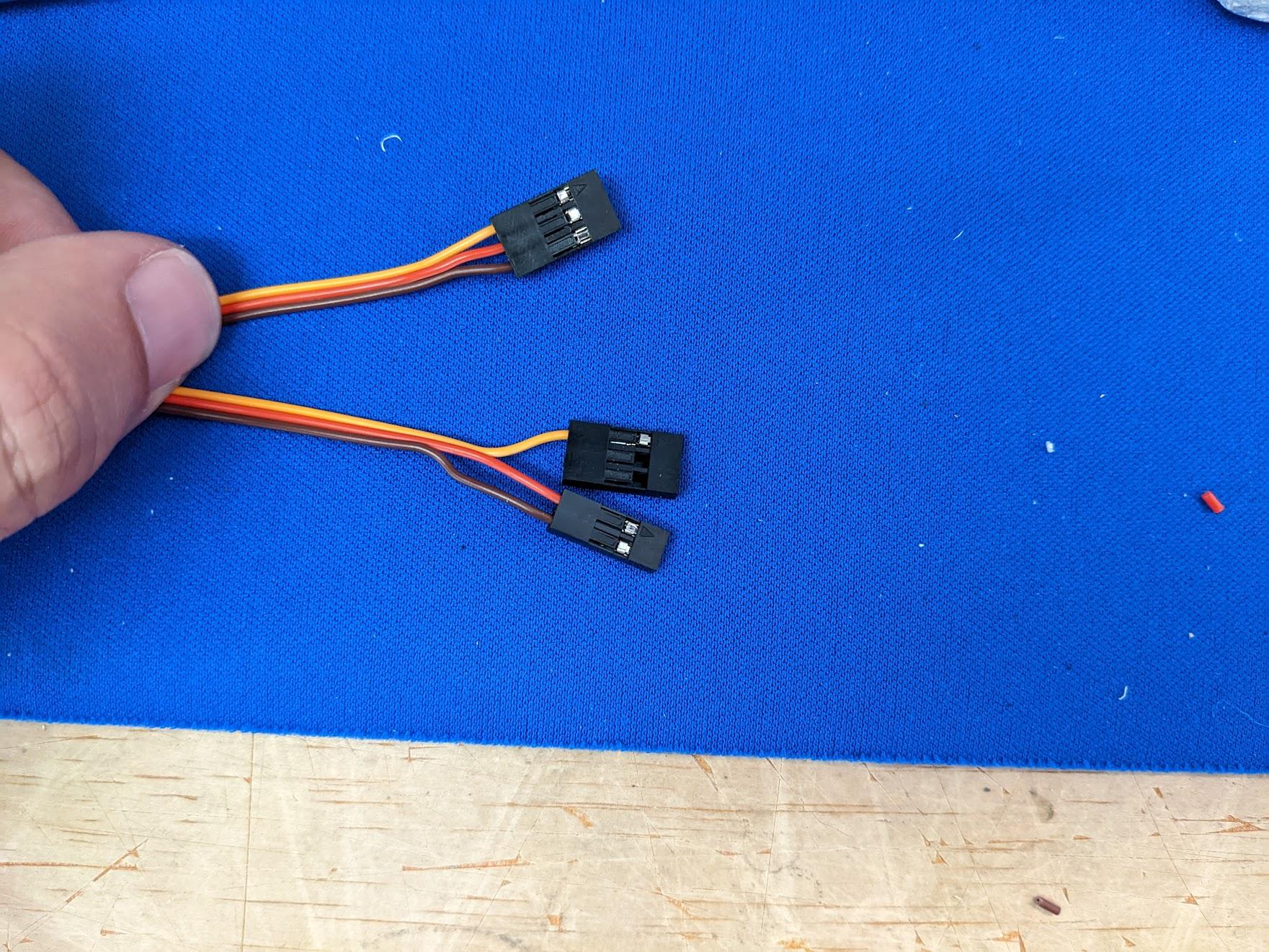
Since the retracts must run from 5V but the H743 is configured to output 7.2V to servos, prepare a 3-way Y-harness with the red power input lead separated. Plug the red BEC lead from one 80A ESC into this lead, while the signal and ground connect to the flight controller.
-
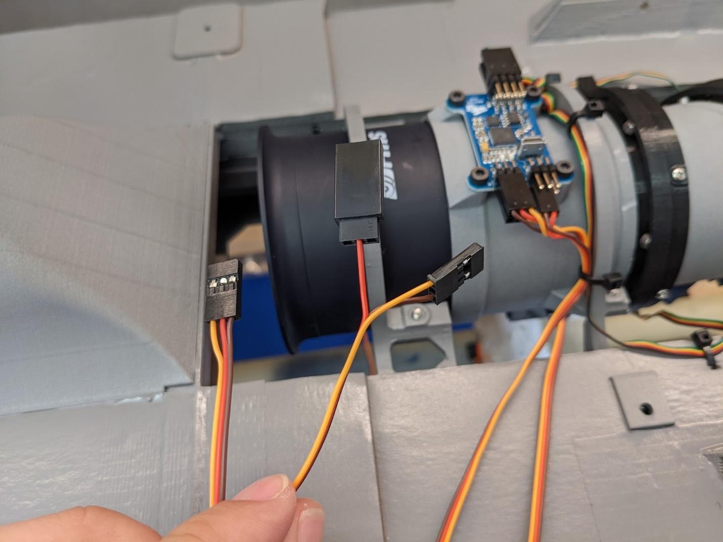
Similarly, prepare a male-to-male extension for the 3BSM controller board that splits the power leads into a separate connector. The 3-pin end of this lead should connect to S7 on the flight controller. The lone signal lead should plug into the rudder input of the 3BSM board, while the power end should plug into one set of the servo power pins on the 3BSM board. This will provide Vx (7.2V) to the servos.
-
Lastly, the second male-to-male extension for the 3BSM controller board should have its red lead split off into a receptacle. This should connect to the red BEC lead from the second 80A ESC, while the signal and ground connect to S8 on the flight controller. The complete 3-pin end should connect to the 3BSM controller's transition input pins. This will provide 5V power to the 3BSM controller board in addition to the tilt signal.
Avionics installation
-
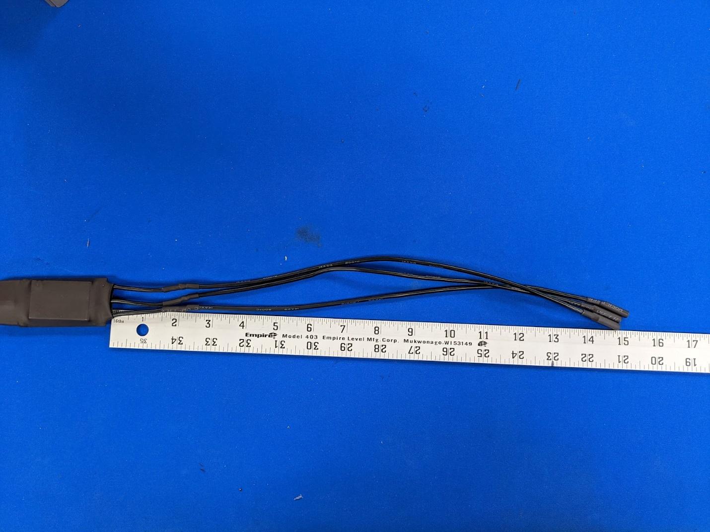
Extend the motor leads on one of the 80A ESCs to the length shown for the lift fan.
-
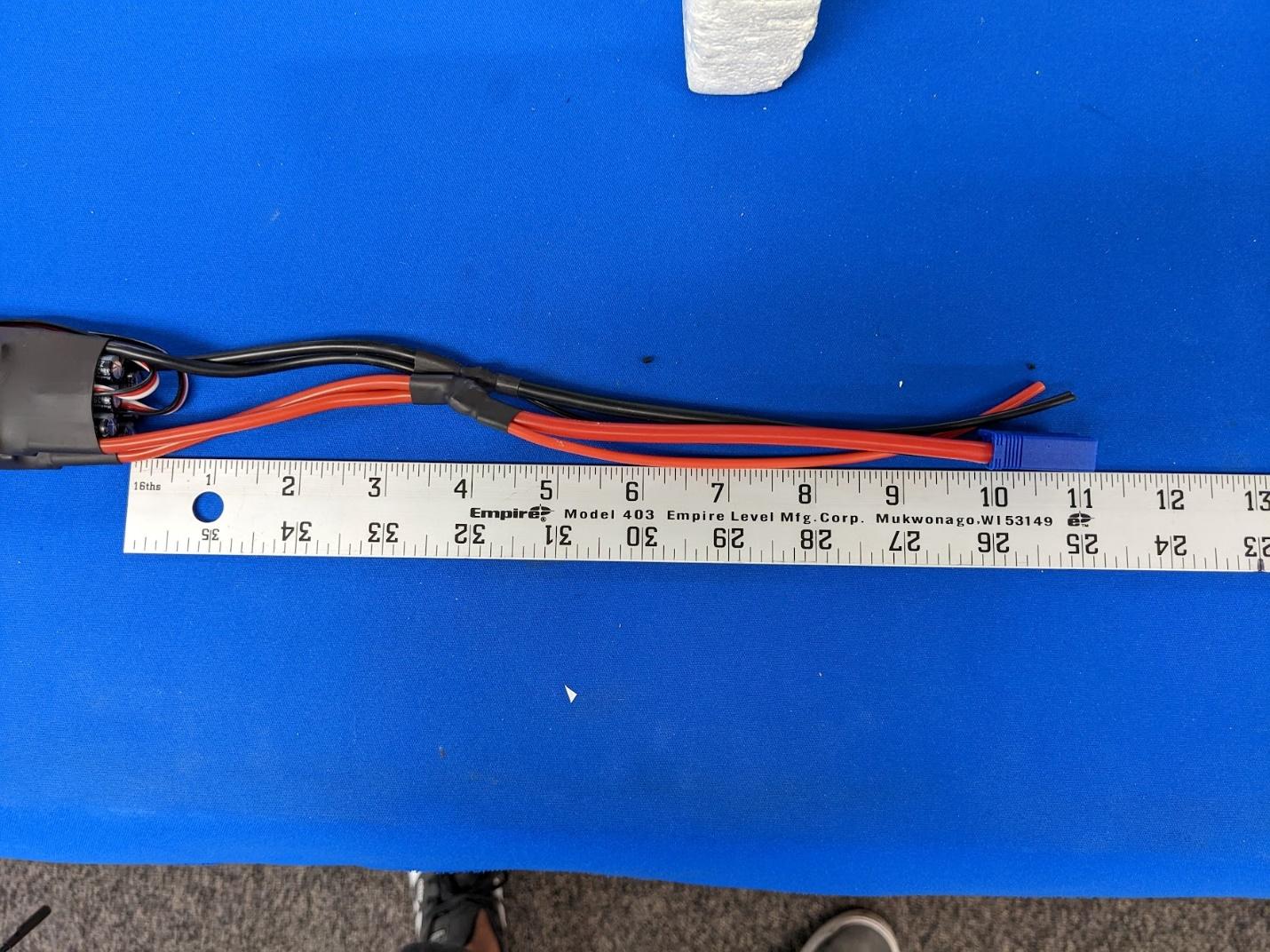
Solder the two main ESCs together with wires of the length shown. Use a length of 10AWG wire for the battery input and a length of 16AWG wire which will connect to the flight controller.
-
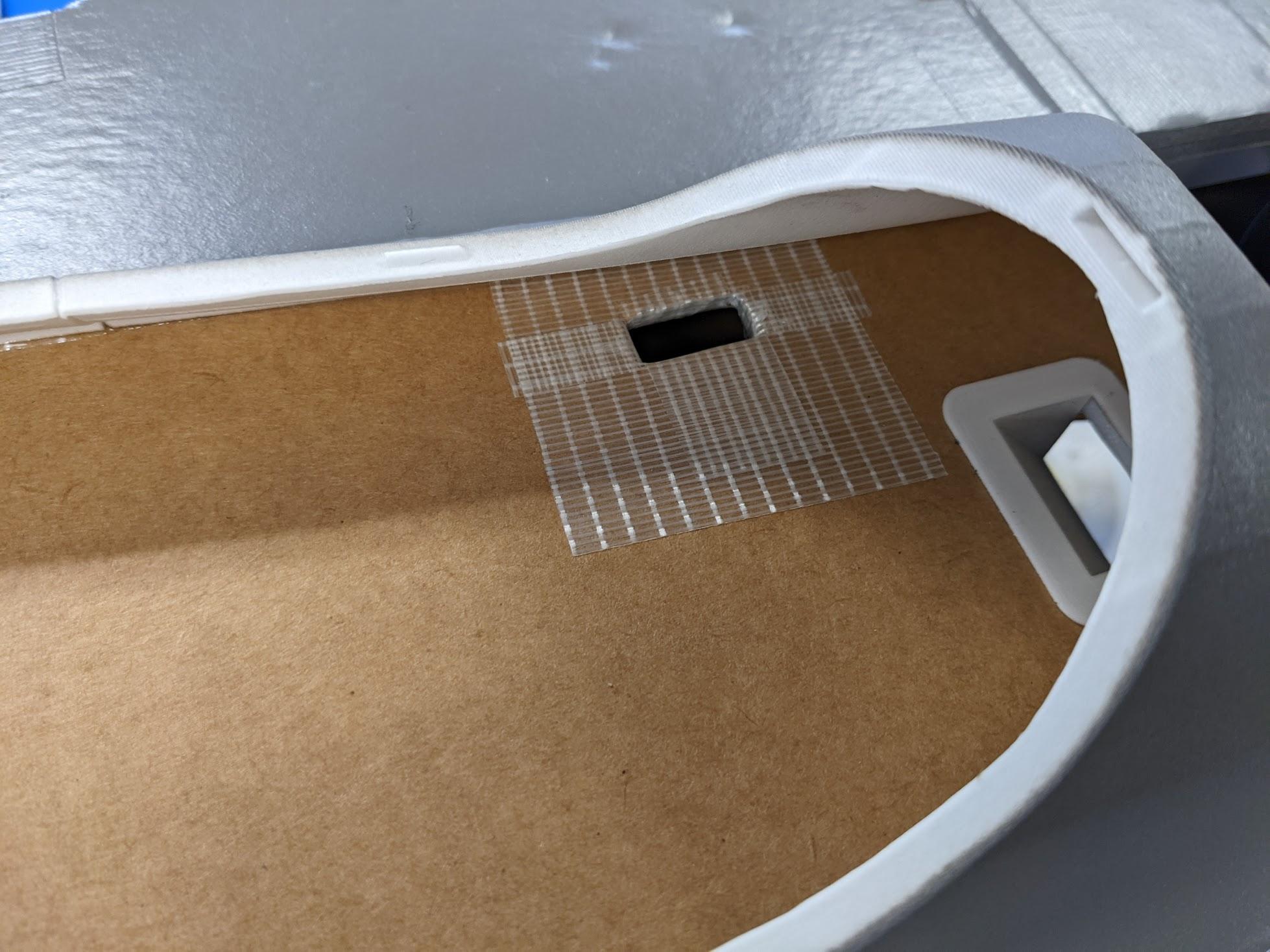
Cut a hole for the battery connector to enter the battery hatch area. Reinforce with strapping tape.
-
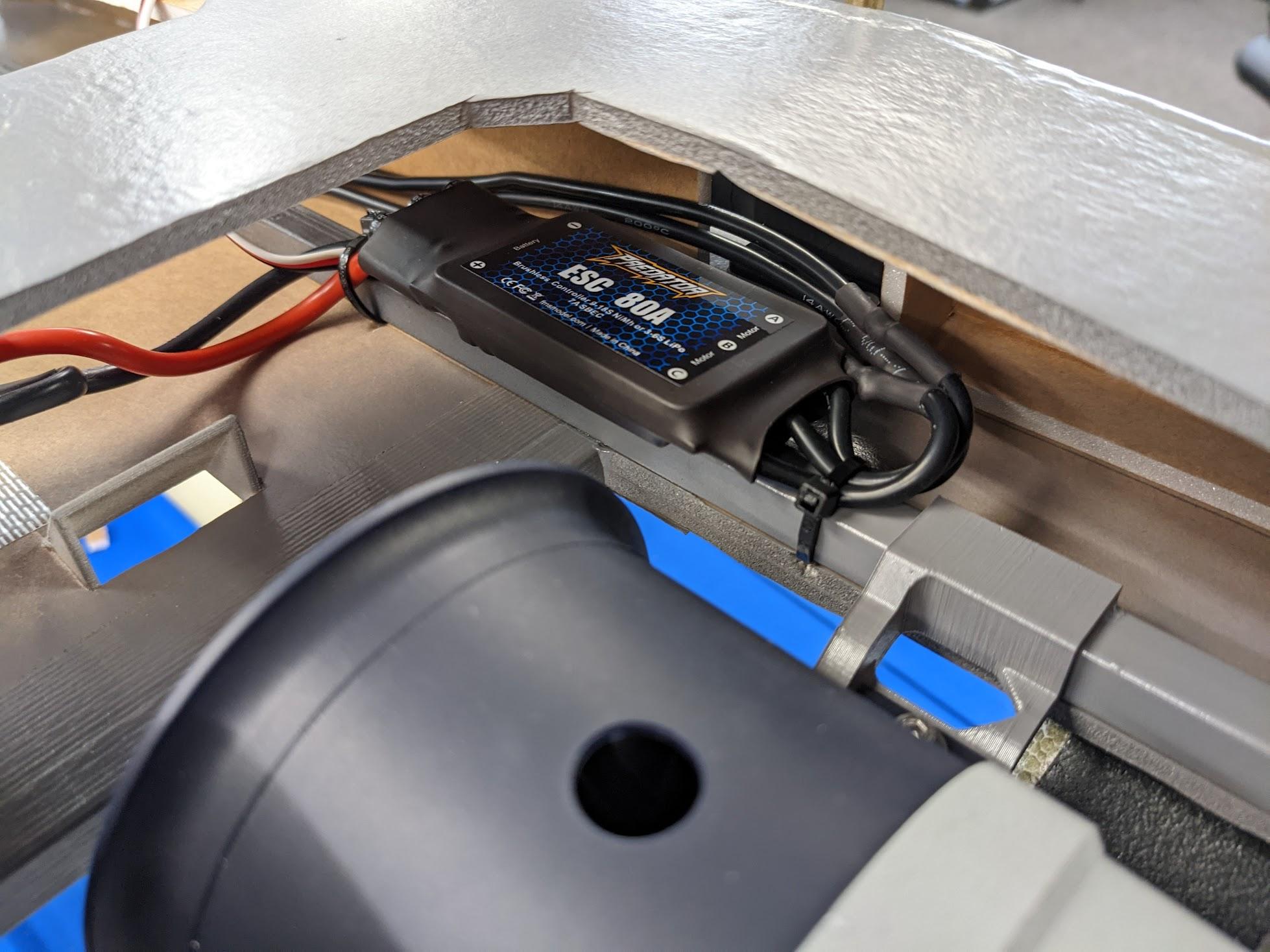
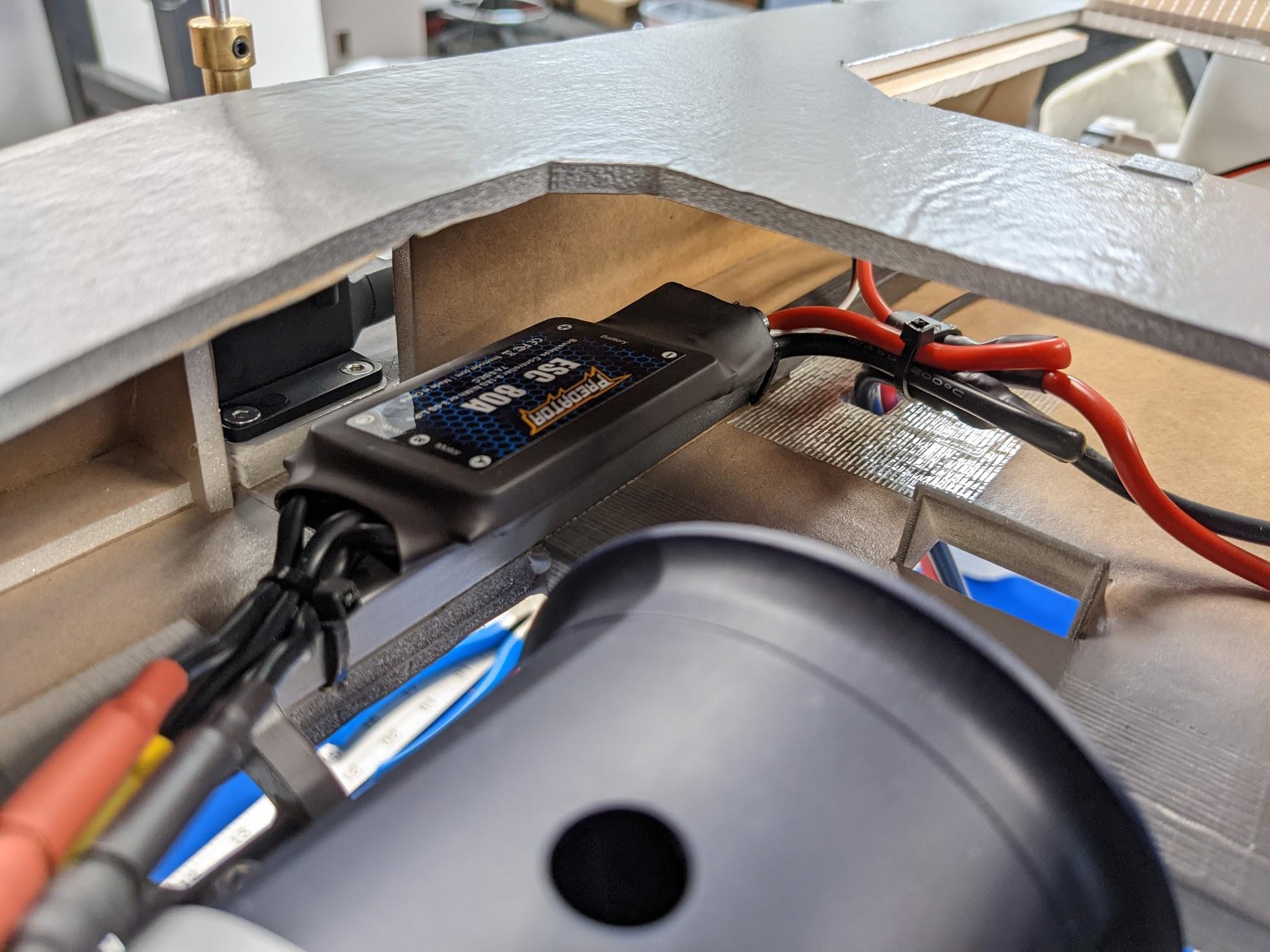
Use double-sided tape and zip ties to attach the ESCs to the fuselage spars. Pass the battery connector through the hole.
-
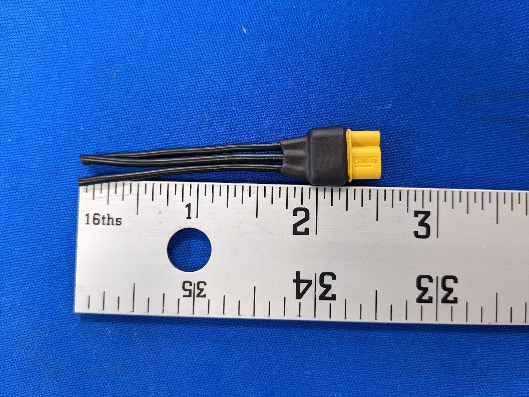
Prepare two MR30 connectors with 22AWG leads for the roll ESCs.
-
Solder the MR30 connectors to the roll ESCs. Connect them to the flight controller with 16AWG wire.
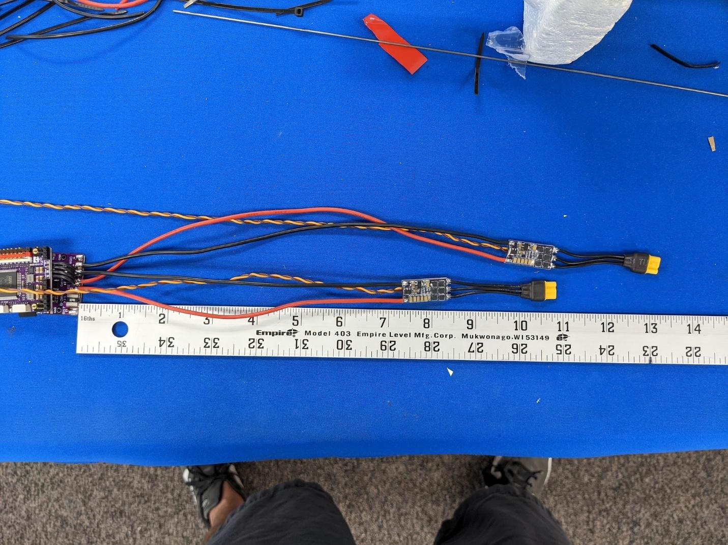
-
Solder the 16AWG battery input leads to the flight controller.
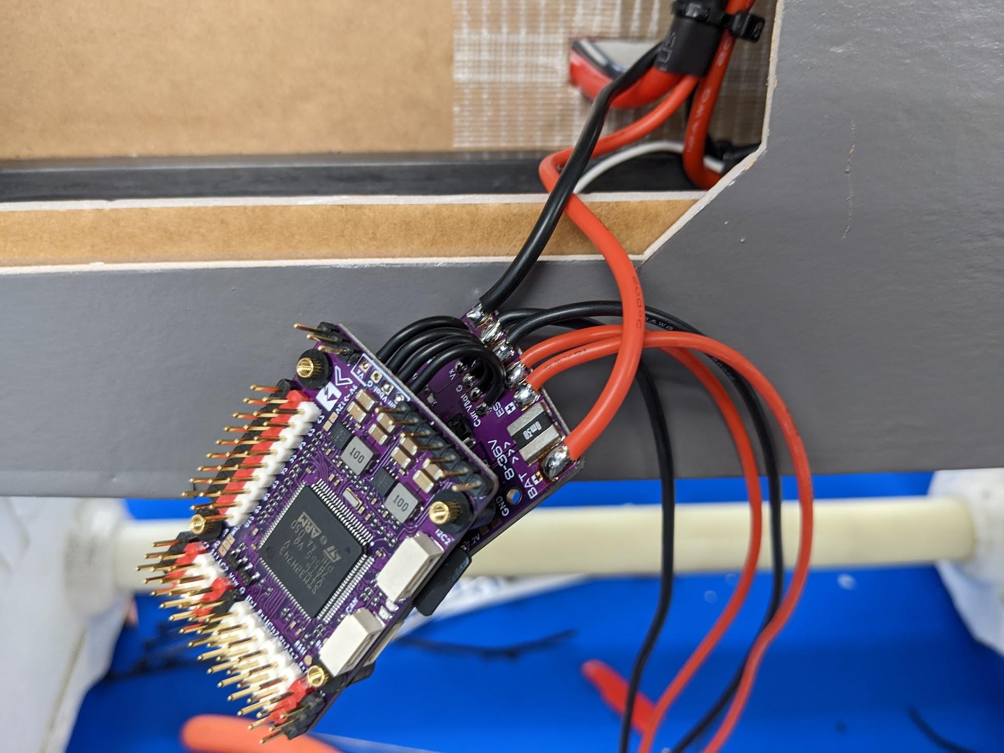
-
Re-stack the flight controller, then use double-sided tape to fix it inside the fuselage. Use one of the battery strap holders to set the spacing. You may wish to load firmware and calibrate before mounting.
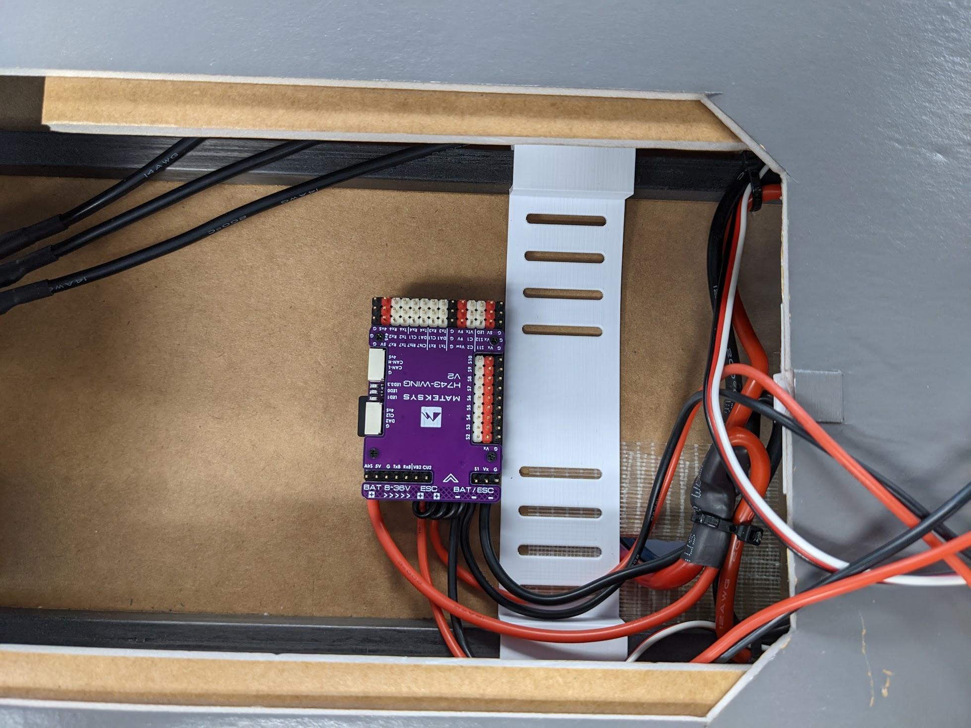
-
Use double-sided tape to adhere the roll ESCs just inboard of the main gear. It may be helpful to temporarily remove the retract units.
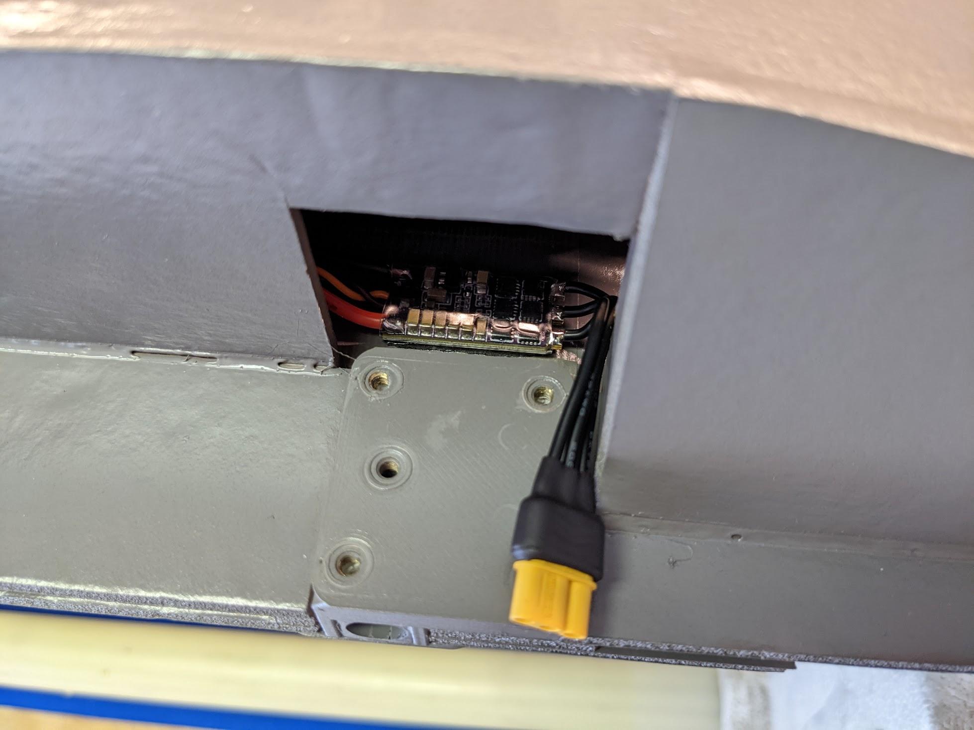
-
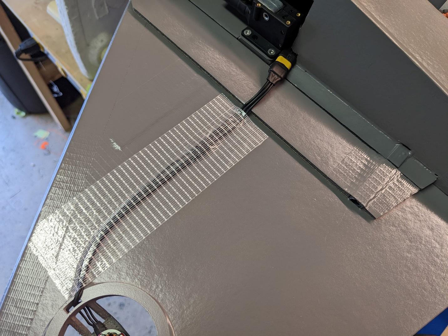
Dry-fit the wing panels and secure the roll motor leads with strapping tape.
-
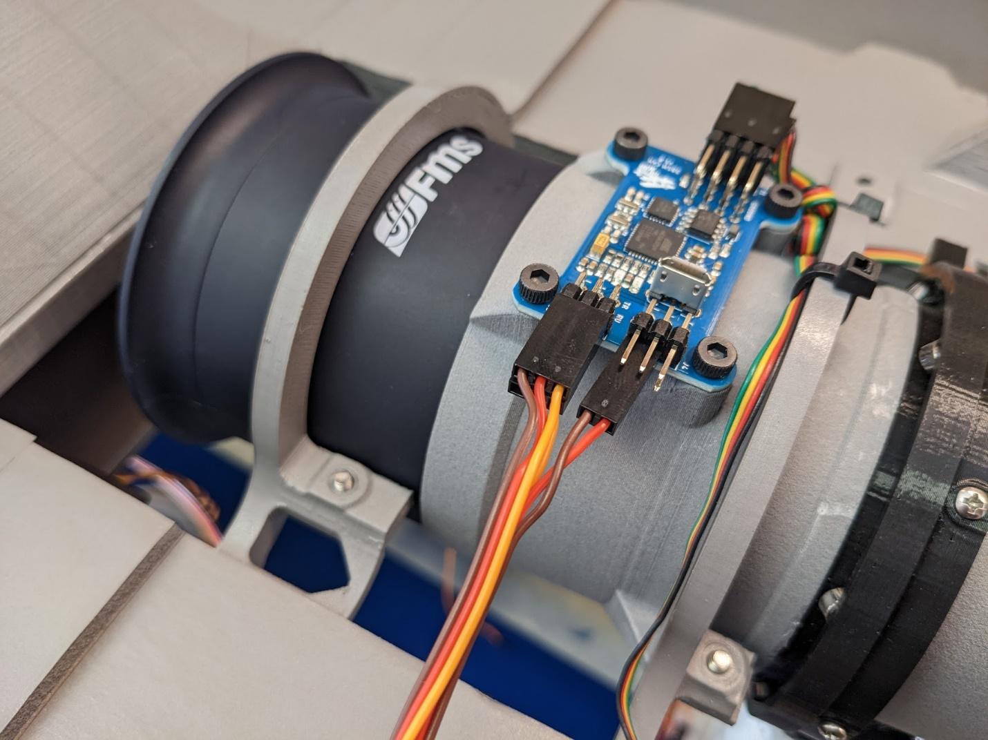
Secure the various leads from the 3BSM servos and control board with cable ties. Ensure that there is enough to allow for the entire range of motion of the 3BSM.
-
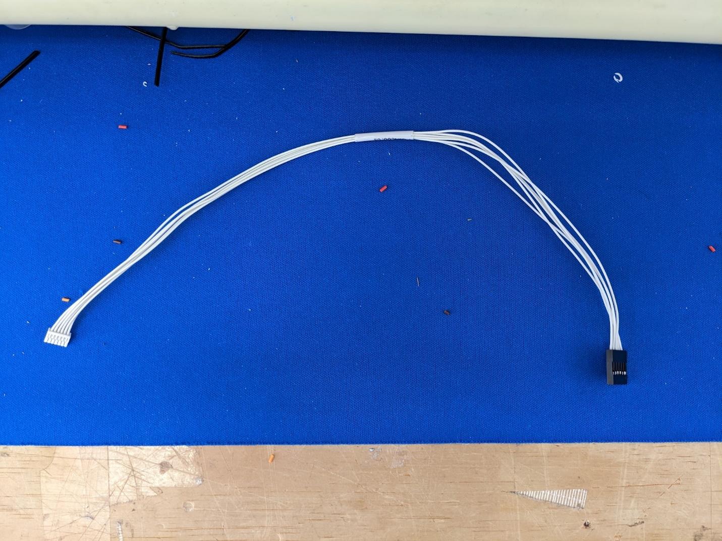
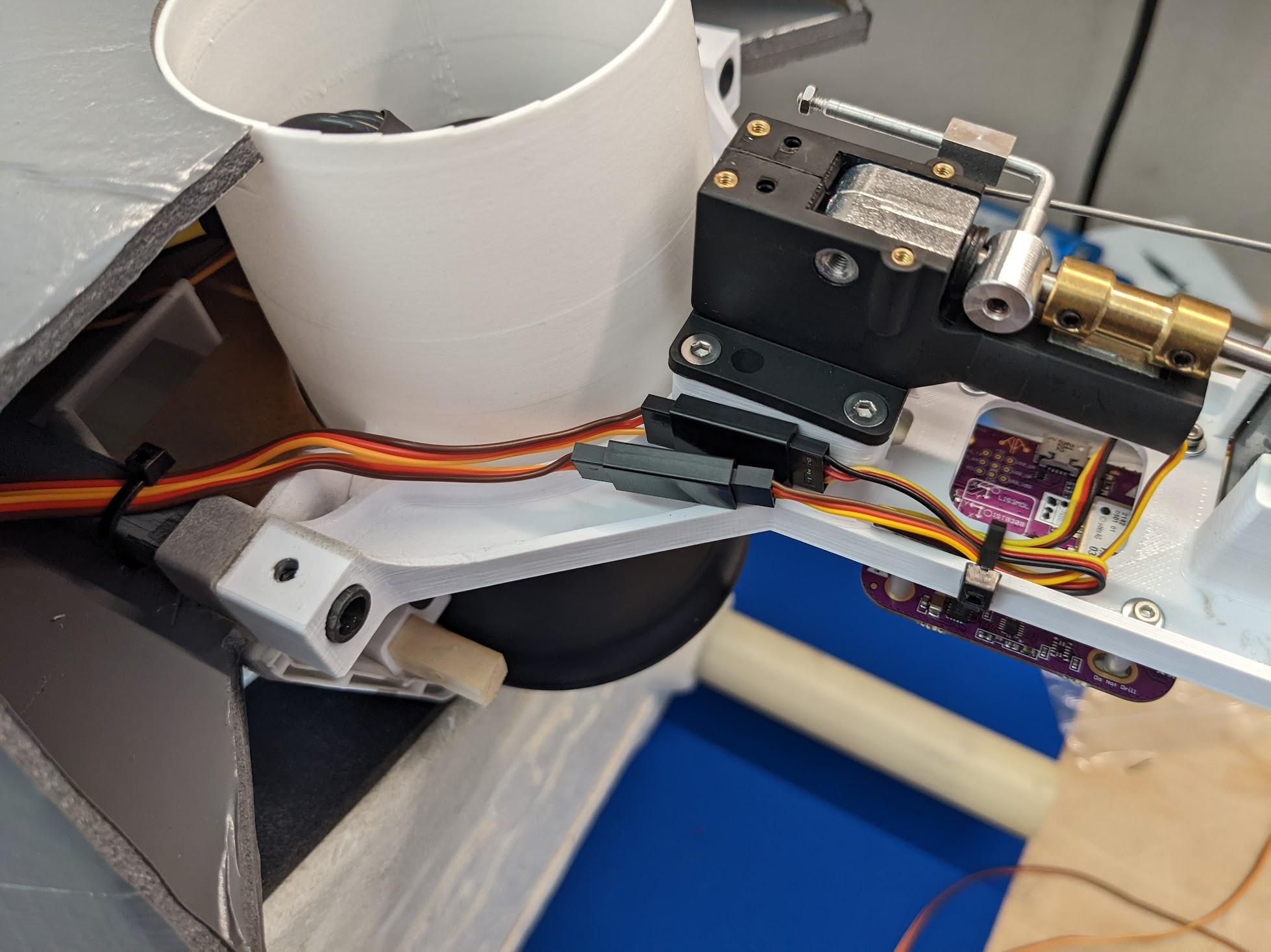
Make a cable to connect the GPS module with a 6-pin JST-GH connector on one end and header pins on the other. Refer to the Matek pinout diagrams.
-
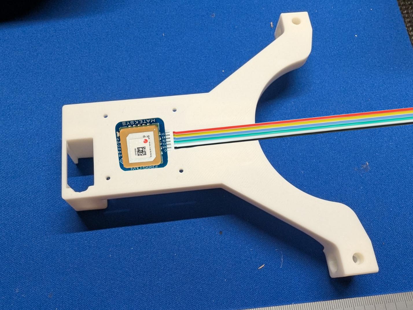
Use double-sided foam tape to attach the GPS module to the nosegear mount in the position shown.
-
Use cable ties to secure the GPS cable along with cables for the nose retract and steering servo.
-
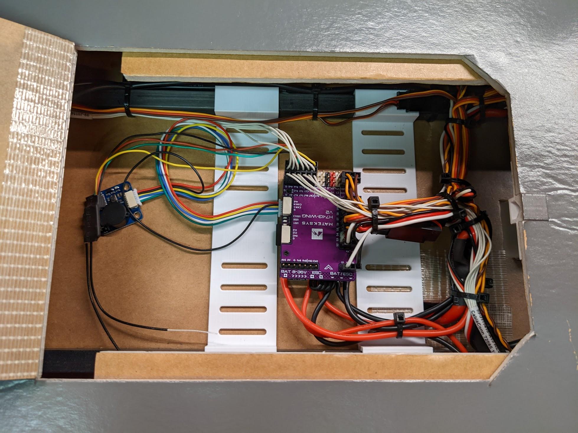
Connect the remaining wiring using the provided diagram. Tidy and secure with cable ties. Glue in the second battery strap holder.
-
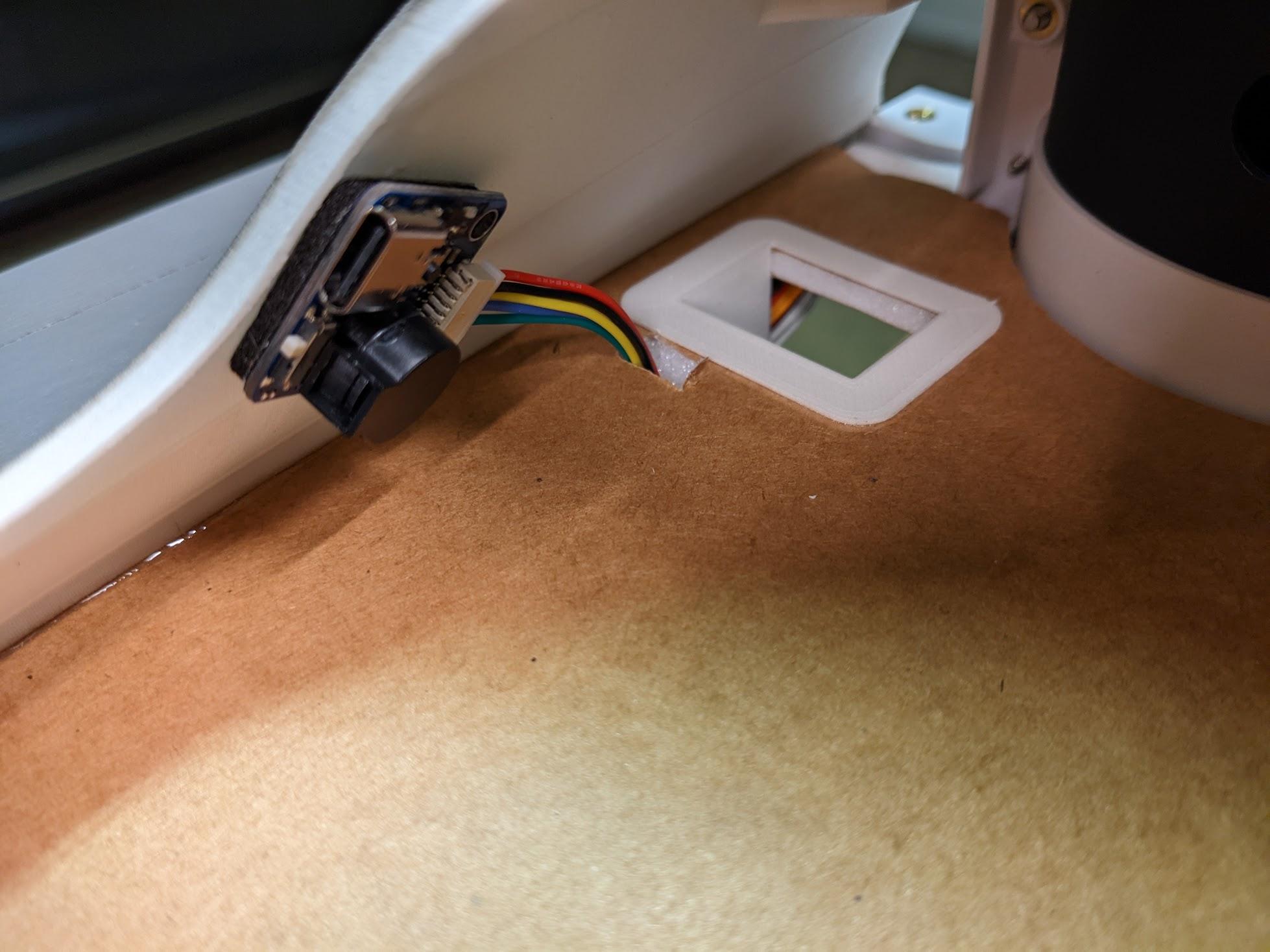
Mount the flight controller's USB extension to an accessible location in the upper fuselage.
-
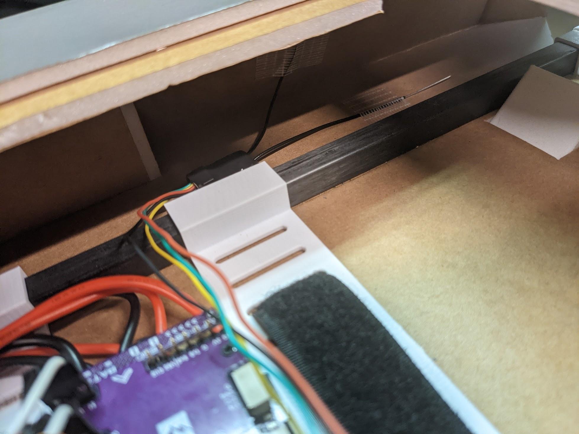
Mount the R/C receiver to an open area inside the lower fuselage.
-
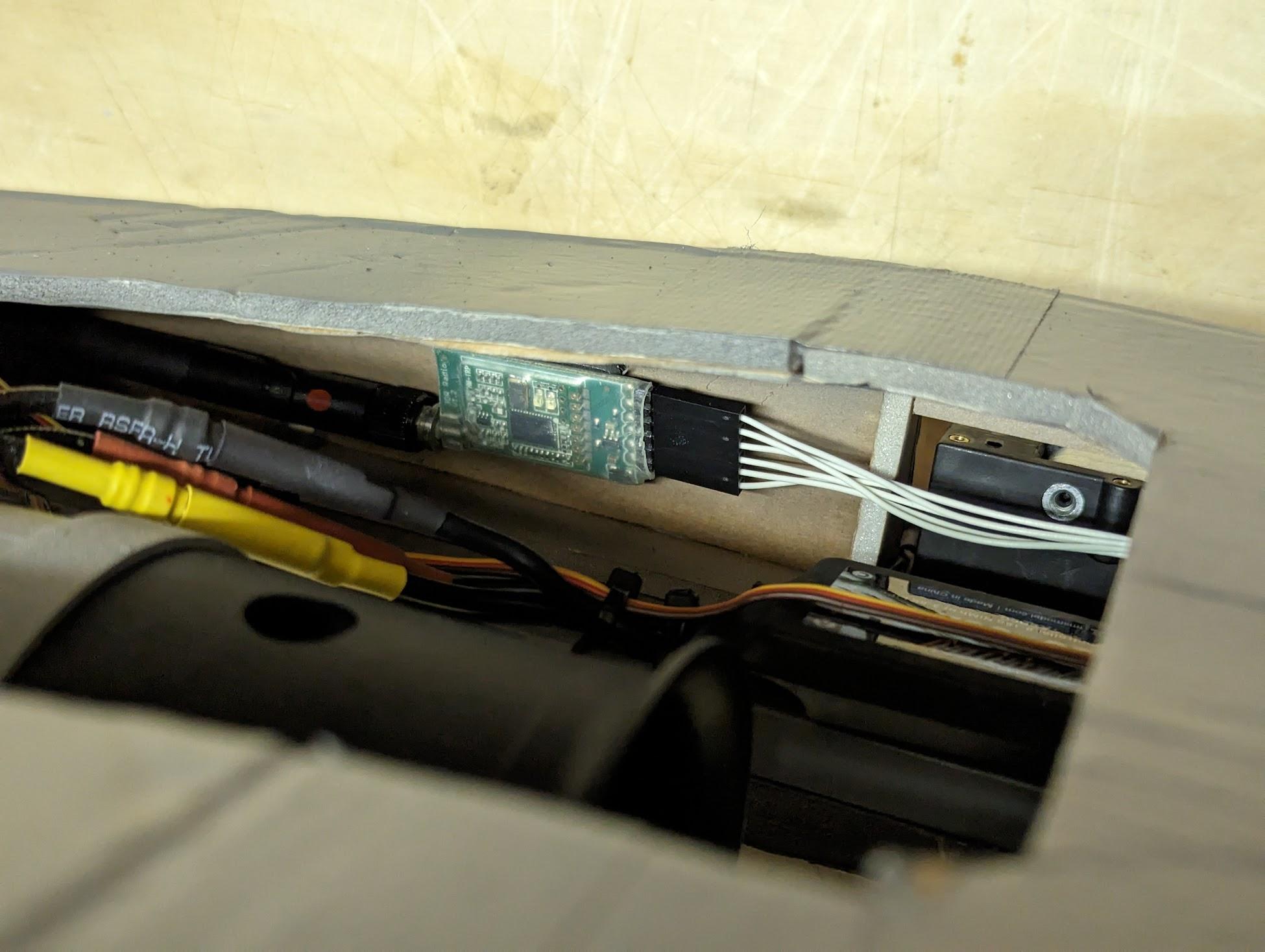
If using a telemetry radio, it can be mounted in the lower fuselage as well. It's a good idea to mount it as far from the R/C receiver and GPS as possible.
Setup & finishing
Refer to the flight controller setup video to load firmware, perform calibrations, and configure ArduPilot for flight. Setup for the 70mm model is the same as the 90mm – just with elevons instead of separate aileron and elevator surfaces and no flaps. See also the Firmware Flashing Guide for ArduPilot on the Matek H743-Wing.
One thing has changed since the video was recorded
The video shows an unnamed, blank entry in Mission Planner's Flight Modes screen. That was a custom flight mode, which used the 3BSM nozzle for longitudinal control in a hover instead of tilting the airframe.
In current firmware this behavior is built into the stock QLOITER mode, so you'll see QLOITER labeled wherever the video shows the custom mode. Everything else in the video still applies.
As mentioned in the video guide, adjust control deflections using the suggested throws below. It is VERY important that throws match these suggestions, as the default stabilization gains will be incorrect otherwise. Dual rates and trim should not be used, as this can interfere with the flight controller's functions in assisted modes. Regardless, consider using 25% - 50% expo for a smooth control response.
Match these throws exactly
| Control (measured at forward-most tip vs. fuselage) | Travel |
|---|---|
| Stabilator — Roll | 22 mm up / 22 mm down |
| Stabilator — Pitch | 22 mm up / 22 mm down |
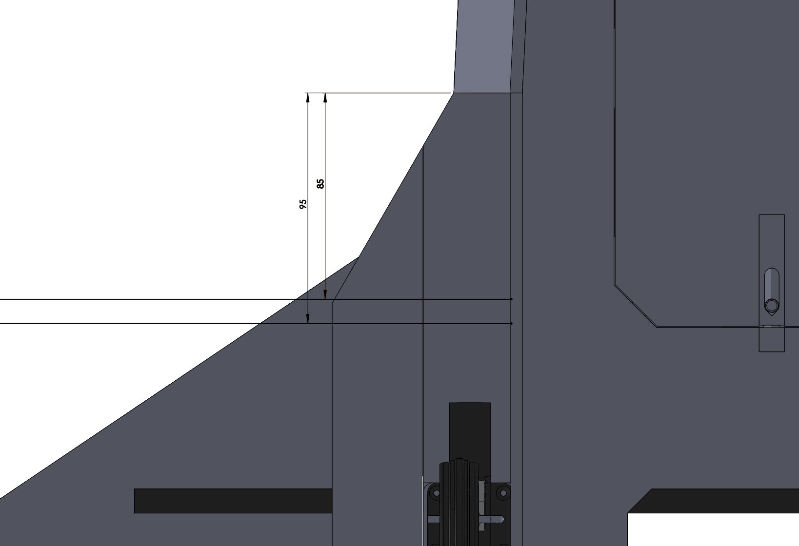
The recommended CG is located at the mark shown, 85mm to 95mm behind the leading edge of the wings at the root. Ensure that the model balances at this location with the battery, electronics, and all hatches installed. The landing gear should be extended during balancing.
Please consider also operating the model in RealFlight, as described in the following video. This simulator runs real ArduPilot firmware and interacts with Mission Planner just like the real model would. Mastering the simulator model is a great way to prepare for the first flights. Again, the 70mm model is effectively the same as the 90mm model shown in the video guide.
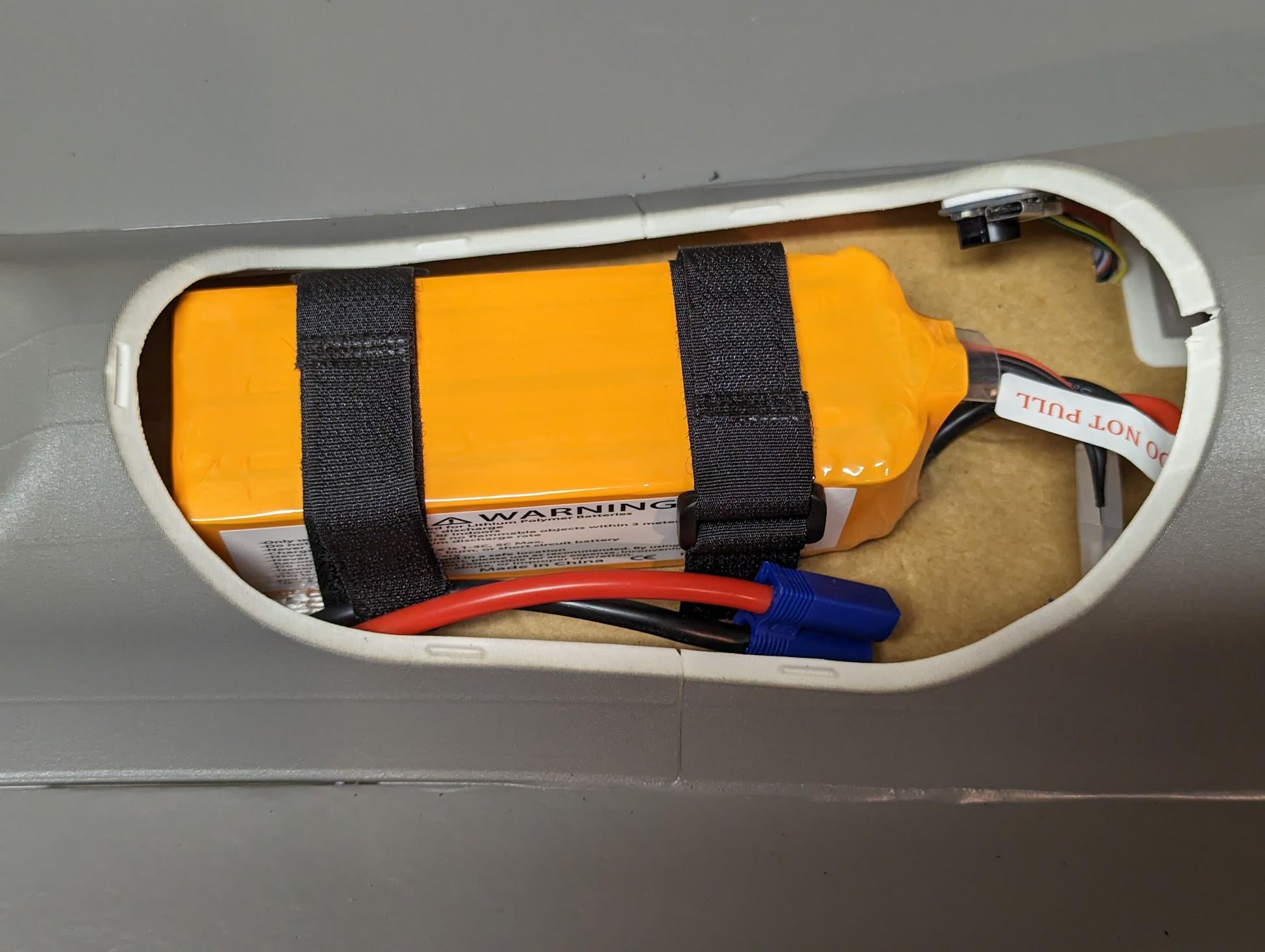
Secure the battery with hook and loop straps.
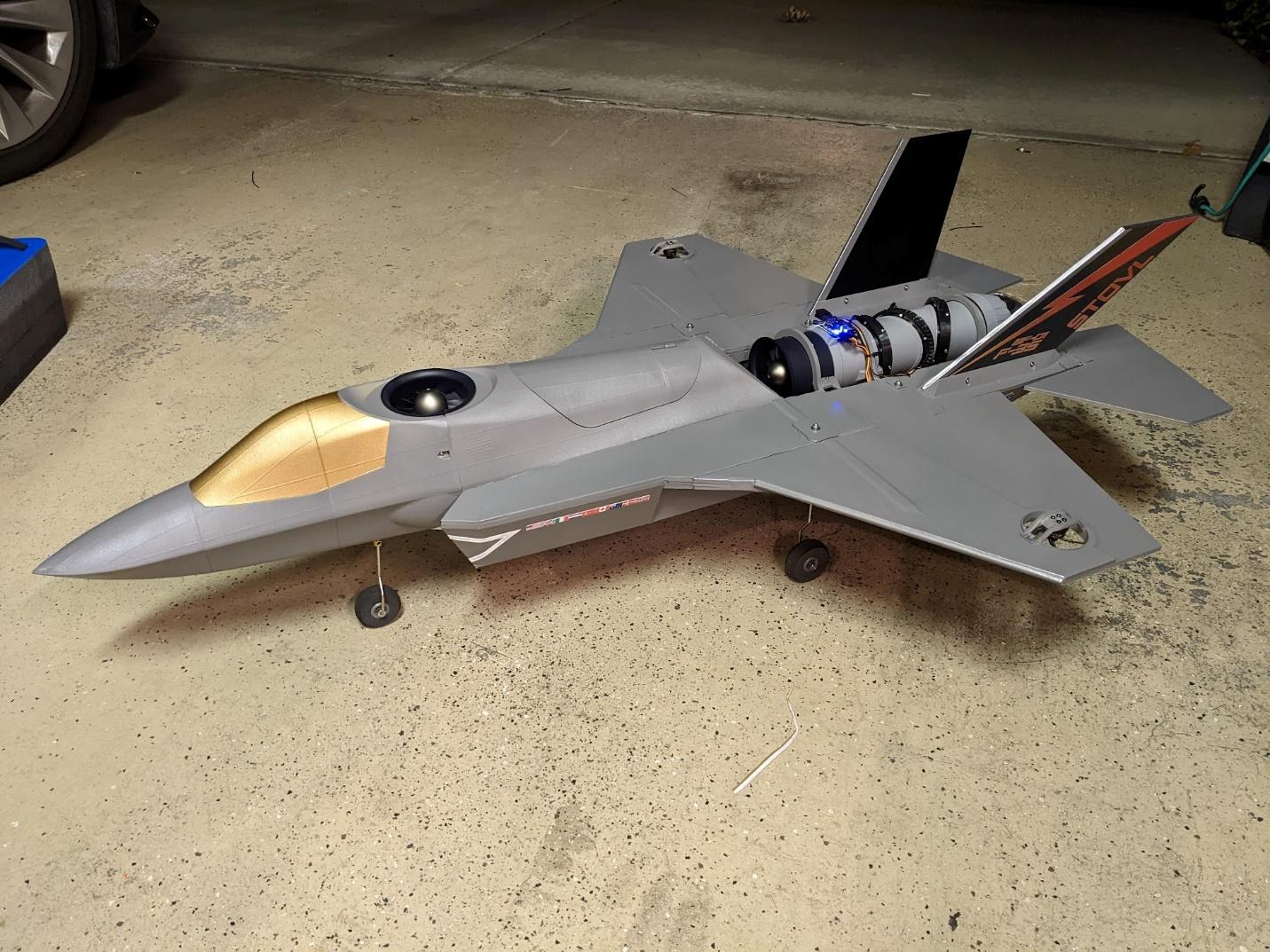
Apply graphics if desired. You're ready to fly!
Contact us
Have a question, issue, or just a cool idea for the next aircraft we should model? Drop us an email at: info@loftedaero.com